Transcription of The Current-Steering DAC
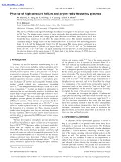
1 A C ircu it for All Seasons Behzad Razavi The Current-Steering DAC. D. Digital-to-analog converters (DACs) component, as in displays and opti- voltage experiences large fluctua- find application in many systems, cal modulators. tions in the presence of parasitic se- including communication trans- The current-switching structure ries inductances, such as those due mitters and consumer electronics. shown in Figure 1(a) suffers from to bond wires. Among various DAC realizations, the dynamic errors. As depicted in Fig Both of these effects can be greatly Current-Steering topology offers the ure 1(b), when a switch turns off, the suppressed through the use of current highest speed and becomes the de top terminal voltage of its correspond- steering (Figure 2). Here, the tail cur- facto solution at gigahertz frequen- ing current source collapses to zero. rent is steered to the left or the right cies, especially if the analog output Thus, the next time that this branch is by each differential pair, causing only a must be delivered to a resistive load.
2 Enabled, the (nonlinear) capacitance at small voltage excursion at node X. Also, In this article, we study this DAC's de- this terminal must charge up, draw- since the total array current is relatively sign principles. ing a significant transient current constant, the ground bounce is much from the output node. Moreover, since smaller. Of course, another advantage Basic Topology switching actions change the total cur- of this configuration is that it naturally We wish to convert an N -b digital rent carried by the array, the ground provides differential outputs. signal, D in, to an analog current, I out. This can be accomplished as illus- trated in Figure 1(a), where each input bit controls a current that is binarily Iout weighted with respect to a unit value, I u. Here, D 1 denotes the least signifi- cant bit (LSB) and D N the most signifi- D1 D2 DN VX. X. cant bit (MSB). The current sources are .. X CX. Vb scaled up by a factor of two from one Iu 2Iu 2N 1Iu bit to the next, yielding t (a) (b).
3 I out =D N (2 N -1 I u) +g+D 2 (2I u) +D 1 I u . (1). Figure 1: (a) A simple binary-weighted current-switching DAC and (b) the problem of This circuit is an example of a simple discharge at X when the switch is off. binary-weighted DAC. We can also call it a current-switching but not a Current-Steering implementation. An important advantage of this +. Iout DAC over other types is its ability to drive resistive loads with no need . Iout for a buffer. This property proves M1 M2. D1 D2 .. DN. crucial if the DAC must drive a trans- X Iu 2Iu 2N 1Iu mission line, as in wireline systems, Vb or if the load contains a resistive W. M3 2W 2N 1W. L L L. Digital Object Identifier Date of publication: 31 January 2018 Figure 2: A binary-weighted Current-Steering DAC. IEEE SOLID-STATE CIRCUITS MAGAZINE W i n t e r 2 0 18 11. and 2 N -2 I u current sources for the VDD VDD VDD former code and by the 2 N -1 I u cur- + + +. RL Vmax RL Vmax rent source for the latter.
4 The differ- R0 R0lSS. ence is nominally equal to 1 LSB = I u, RD RD. VDD Dj M 1 M2 Dj M1 M2 but, with mismatches present in the circuit, it is possible that the sum 0 X X. Dj of t he for mer g r oup is subst a n - M3 tially different from 2 N -1 I u - I u . As M3 lSS. VDD. a result, the DAC input output char- acteristic can exhibit a large error or nonmonotonicity at this transi- t tion (Figure 4). The fundamental (a) (b) difficulty here is that, at this major carry transition, a group of current Figure 3: A DAC cell with (a) rail-to-rail or (b) moderate digital swings. sources turns off and a new current source turns on. For proper matching among the The foregoing issue can be avoided current sources, we design a unit cell by segmentation. For an N -b DAC, Iout comprising a current source and a we still incorporate 2 N - 1 unit cells differential pair and repeat this cell but apply a different switching se- to form larger cells. That is, cell num- quence.
5 As shown in Figure 5, for a ber j consists of 2 j -1 unit cells in binary input 000g01, one cell is ac- parallel, and the entire DAC contains tivated; for 00g10, two; for 00g11, 2 N - 1 unit cells. three; etc. We say the cells are driven One drawback of Current-Steering by a thermometer code. For exam- DACs is their limited output voltage ple, as the binary input goes from 01. 011111. 100000. Din compliance. In Figure 2, for example, to 10 to 11, the corresponding ther- the differential-pair transistors must mometer code changes from 0001 to Iout operate in saturation (as explained 0011 to 0111. below), and, therefore, at least two The segmented architecture avoids drain-source voltages are subtracted the jumps shown in Figure 4 because, from the supply, VDD. at the major carry transition, it sim- Another difficulty in the design is ply turns on one more LSB cell, rather the choice of the digital input volt- than turn off one group of current age excursions.
6 The most convenient sources. Thus, the output changes are rail-to-rail swings, but, as shown monotonically, and the jump is not 011111. 100000. Din in Figure 3(a), such a choice 1) limits much different from 1 LSB as the new the analog output voltage range Vmax cell has some matching with respect to one transistor threshold if M 1 to the previous cells. In practice, of Figure 4: Large jumps or nonmonotonicity must remain in saturation and 2) course, each cell is based on a current- in binary-weighted DAC characteristics due leads to large dips in VX during the steering structure. to mismatches. transitions of D j and D j . In other words, we would prefer only a mod- Partial Segmentation erate swing for the digital inputs, We have seen that the number of unit with a maximum level less than VDD cells is the same for binary and seg- so as to allow a greater Vmax. Such mented architectures and becomes 2N 1 Units Iout swings call for another differential prohibitively large at high resolu- pair [Figure 3(b)] and hence substan- tions.
7 For example, a 10-b DAC would tial power consumption. require 1,023 cells, facing severe X .. Iu Iu Iu area and routing issues. We note, The Need for Segmentation however, that the matching require- The binary-weighted arrays in Fig- ments are more relaxed for the LSB. Binary Thermometer Decoder ure 1(a) or Figure 2 can face undesir- current sources: even if the first and able jumps in their output when the second LSB currents have a mismatch Binary Input digital input goes from 011g1 to of 10%, the overall characteristic can 10g0. We observe that the output still reach 10-b precision. Let us con- Figure 5: A segmented DAC. current is provided by the I u, 2I u, f, sider the following approach: rather 12 W i n t e r 2 0 18 IEEE SOLID-STATE CIRCUITS MAGAZINE. than copy currents by means of unit cells, we seek a method of dividing Binary Section Segmented Section currents by binary factors. For exam- LSB3 LSB2 LSB1. ple, we can keep doubling the length lu lu of the current-source transistors, as lu lu lu 2 4.
8 Lu lu W. shown in Figure 6(a). However, the lu W W W W. vb 4 2 .. L L. L L L. effective length does not double, cre- W W. W W W. ating significant errors. Instead, we 4L 2L L L L. vb W. place identical transistors in series (a) L. [Figure 6(b)]. The resulting architec- W. ture is called a partially segmented L. DAC to emphasize that only the MSB. (b). section is segmented. The exact partitioning of the DAC. Figure 6: (a) Binary weighting by doubling transistor lengths and (b) a partially segmented into segmented and binary sections DAC employing transistors in series. depends on the matching properties of the transistors; the binary array can still suffer from effects shown in Figure 4. In a typical design, we Iout use binary weighting for the first three or four LSBs and segmentation for the remaining bits.. INLmax vb P. Static Errors .. Current-Steering DACs must deal with Din three types of static errors. First, the (a) (b). random mismatches among the cur- VDD.
9 Rent sources distort the input output RL. characteristic. These mismatches Iout Vout accumulate and primarily manifest themselves in the form of integral nonlinearity (INL) in segmented to- .. pologies. Illustrated in Figure 7(a), Iu ro Iu ro Iu ro the INL is defined as the error be- tween the actual characteristic and Din (c) (d). a straight line passed through its points. Second, the voltage drop along the ground line traveling to the cur- Figure 7: (a) An illustration of INL, (b) the effect of ground line IR drops, (c) the effect of output impedance of current sources, and (d) a compressed characteristic arising from (c). rent cells can cause significant deter- ministic nonlinearity. As depicted in Figure 7(b), if a large number of cells inject current into a long ground line, voltage change equal to I u (R L | | rO) Since differential operation sup- the voltage at the farthest point from and the last, I u [R L | | (rO /M )]. Due presses even harmonics, we expect ground, P, can reach tens of milli- to this code-dependent output resis- the differential counterpart of the volts.
10 With a nominal overdrive volt- tance, the input output charac- array in Figure 7(c) to achieve a higher age of, say, 200 mV for the current teristic exhibits compression as linearity or, for a given INL, require a sources, the ground drop introduces D in increases [Figure 7(d)]. It can be less stringent output resistance. excessive nonlinearity. shown that the maximum INL aris- The third static error relates to the ing from this effect is given by Dynamic Errors finite output resistance of the cells I u R 2L M 2 / (4rO), which, normalized to The Current-Steering DAC of Figure 2. if the DAC must drive a resistance. the full-scale output voltage, is ap- also suffers from dynamic errors, From Figure 7(c), we observe that the proximately equal to MR L / (4rO). For and hence greater distortion, at high incremental resistance at the output example, if M = 1024 and R L = 50 X, output frequencies. We examine three node varies from R L | | rO when only then rO must exceed MX for the such errors here.