Transcription of UNDERSTANDING RELAYS - Autoshop 101
1 UNDERSTANDING RELAYSPage 1 , All Rights Reserved. This Automotive SeriesUNDERSTANDING RELAYShas been developed byKevin R. SullivanProfessor ofAutomotive TechnologySkyline CollegeAll Rights ReservedRELAYSR elays are used throughout the automobile. RELAYS which come in assorted sizes, ratings,and applications, are used as remote control switches. A typical vehicle can have 20 relaysor RELAYSPage 2 Autoshop , All Rights LOCATIONSR elays are located throughout the entire vehicle. Relay blocks, both large and small, arelocated in the engine compartment; behind the left or right kick panels, or under the dashare common locations.
2 RELAYS are often grouped together or with other components likefuses or placed by POSITION IDENTIFICATIONR elay / Fuse block covers usually label the location and position of each fuse, relay, or fuseelement contained RELAYSPage 3 Autoshop , All Rights APPLICATIONSR elays are remote control electrical switches that are controlled by another switch, such asa horn switch or a computer as in a power train control module. RELAYS allow a small currentflow circuit to control a higher current circuit. Several designs of RELAYS are in use today, 3-pin, 4-pin, 5-pin, and 6-pin, single switch or dual switches. UNDERSTANDING RELAYSPage 4 Autoshop , All Rights Reserved.
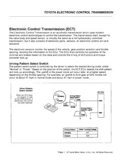
3 RELAY OPERATIONAll RELAYS operate using the same basic principle. Our example will use a commonly used 4 -pin relay. RELAYS have two circuits: A control circuit (shown in GREEN) and a load circuit(shown in RED). The control circuit has a small control coil while the load circuit has aswitch. The coil controls the operation of the switch. RELAY ENERGIZED (ON)Current flowing through the control circuit coil (pins 1 and 3) creates a small magnetic fieldwhich causes the switch to close, pins 2 and 4. The switch, which is part of the load circuit,is used to control an electrical circuit that may connect to it. Current now flows through pins2 and 4 shown in RED, when the relay in RELAYSPage 5 Autoshop , All Rights Reserved.
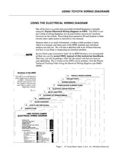
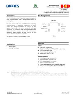
4 RELAY DE-ENERGIZED (OFF)When current stops flowing through the control circuit, pins 1 and 3, the relay becomes de-energized. Without the magnetic field, the switch opens and current is prevented fromflowing through pins 2 and 4. The relay is now OFF. RELAY OPERATIONWhen no voltage is applied to pin 1, there is no current flow through the coil. No currentmeans no magnetic field is developed, and the switch is open. When voltage is supplied topin 1, current flow though the coil creates the magnetic field needed to close the switchallowing continuity between pins 2 and RELAYSPage 6 Autoshop , All Rights DESIGN IDRelays are either Normally Open or Normally Closed.
5 Notice the position of the switches inthe two RELAYS shown below. Normally open RELAYS have a switch that remains open untilenergized (ON) while normally closed RELAYS are closed until energized. RELAYS are alwaysshown in the de-energized position (no current flowing through the control circuit - OFF).Normally open RELAYS are the most common in vehicles; however either can be use inautomotive Open (NO)Normally Closed (NC)NORMALLY CLOSED RELAYSThe operation of a Normally Closed relay is the same to that of a Normally Open relay,except backwards. In other words, when the relay control coil is NOT energized, the relayswitch contacts are closed, completing the circuit through pins 2 and 4.
6 When the controlcoil is energized, the relay switch contacts opens, which breaks the circuit open and nocontinuity exists between pins 2 and - ENERGIZED (OFF) ENERGIZED (ON) UNDERSTANDING RELAYSPage 7 Autoshop , All Rights RELAY DESIGNC urrent flows through the control coil, which is wrapped around an iron core. The iron coreintensifies the magnetic field. The magnetic field attracts the upper contact arm and pulls itdown, closing the contacts and allowing power from the power source to go to the load. UNDERSTANDING RELAYSPage 8 Autoshop , All Rights VARIATIONSO ther relay variations include three and five pin RELAYS .
7 A 3-PIN relay instead of two B+input sources, this relay has one B+ input at pin 1. Current splits inside the relay, supplyingpower to both the control and load circuits. A 5-PIN relay has a single control circuit, buttwo separate current paths for the switch: One when the relay is de-energized (OFF - nocurrent through the control coil) and the other the energized (ON - current is flowingthrough the control coil). When the 5-PIN relay is de-energized (OFF), pins 4 and 5 havecontinuity. When the relay is energized (ON), pins 3 and 5 have - PIN4 - PIN5 - PINISO STANDARDIZED RELAYSISO RELAYS were designed to try and standardize relay connections, making it easier to testand design systems.
8 ISO RELAYS are currently used by almost all automotive manufacturerstoday. Both 4 and 5 pin designs are used in both standard mini and micro sizes. FYI: ISO isshort for International Standard MINI SHOWNUNDERSTANDING RELAYSPage 9 Autoshop , All Rights MINI ISO RELAYS TYPESB elow are two popular standard MINI ISO relay configurations. The size of a ISO StandardMINI relay is a 1" square cube. Both 4 and 5 pins designs are PINMINI RELAY4 PINMINI RELAYUNDERSTANDING RELAYSPage 10 Autoshop , All Rights MICRO RELAY TYPESB elow are two popular MICRO ISO relay configurations. The size of a ISO MICRO relay is a1" x 1" x 1/2" square (1/2 as thick as a Mini relay).
9 Both 4 and 5 pins designs are PINMICRO RELAY4 PINMICRO RELAYUNDERSTANDING RELAYSPage 11 Autoshop , All Rights SPIKESWhen the switch is closed (shown left), current flows through the coil from positive tonegative as shown in red. This current flow creates a magnetic field around the coil. The topof the coil is positive, and the bottom is the switch is opened (shown on right), current stops flowing through the controlcircuit coil, and the magnetic field surrounding the coil cannot be maintained. As themagnetic field collapses across the coil, it induces a voltage into itself, creating a reversepolarity voltage spike of several hundred volts.
10 Although the top of the coil is still 12 voltspositive, the bottom of the coil produces several hundred positive volts (200+ volts ormore); 200 is "more positive" and stronger than 12 volts, so current flows from the bottomof the coil up towards the top. UNDERSTANDING RELAYSPage 12 Autoshop , All Rights SUPPRESSION RELAYSR elays are often controlled by a computer. When RELAYS are controlled by semiconductorssuch as transistors, they require some type of voltage suppression device. Solid statecircuits are vulnerable to voltage spikes. Voltage spikes slam against transistors, destroyingthem. While some computer circuits have voltage suppression built inside the computer,others rely on voltage suppression from within the relay.