Transcription of USB 2.0 Hi-Speed Hub Controller
1 2010 - 2015 Microchip Technology 1 General DescriptionThe Microchip USB251xB/xBi hub is a family of low-power, configurable, MTT (multi transaction translator)hub Controller IC products for embedded USB solu-tions. The x in the part number indicates the number ofdownstream ports available, while the B indicates bat-tery charging support. The Microchip hub supports low- speed , full- speed , and Hi-Speed (if operating as a Hi-Speed hub) downstream devices on all of the enableddownstream High performance, low-power, small footprint hub Controller IC with 2, 3, or 4 downstream ports Fully compliant with the USB Specification [1] Enhanced OEM configuration options available through either a single serial I2C EEPROM, or SMBus slave port MultiTRAKTM- High-performance multiple transaction trans-lator which provides one transaction transla-tor per port PortMap- Flexible port mapping and disable sequenc-ing PortSwap- Programmable USB differential-pair pin loca-tions ease PCB design by aligning USB sig-nal lines directly to connectors PHYB oost- Programmable USB signal drive strength for recovering signal integrity using 4-level driv-ing strength resolutionFeatures USB251xB/xBi products are fully footprint com-patible with USB251x/xi/xA/xAi products as direct drop-in replacements Cost savings include using the same PCB components and application of USB-IF Compliance by Similarity Full power management with individual or ganged power control of each downstream port Fully integrated USB termination and pull-up/pull-down resistors
2 Supports a single external V supply source; internal regulators provide V internal core volt-age Onboard 24 MHz crystal driver or external 24 MHz clock input Customizable vendor ID, product ID, and device ID 4 kilovolts of HBM JESD22-A114F ESD protection (powered and unpowered) Supports self- or bus-powered operation Supports the USB Battery Charging specification Rev. for Charging Downstream Ports (CDP) The USB251xB/xBi offers the following packages:- 36-pin SQFN (6x6 mm) (Preferred)- 36-pin QFN (6x6 mm) (Legacy) USB251xBi products support the industrial tem-perature range of -40 C to +85 C USB251xB products support the extended com-mercial temperature range of 0 C to +85 C Applications LCD monitors and TVs Multi-function USB peripherals PC motherboards Set-top boxes, DVD players, DVR/PVR Printers and scanners PC media drive bay Portable hub boxes Mobile PC docking Embedded systemsUSB251xB/xBiUSB Hi-Speed Hub ControllerUSB251xB/xBiDS00001692C-page 2 2010 - 2015 Microchip Technology OUR VALUED CUSTOMERSIt is our intention to provide our valued customers with the best documentation possible to ensure successful use of your Microchipproducts.
3 To this end, we will continue to improve our publications to better suit your needs. Our publications will be refined andenhanced as new volumes and updates are introduced. If you have any questions or comments regarding this publication, please contact the Marketing Communications Department viaE-mail at We welcome your Current Data SheetTo obtain the most up-to-date version of this data sheet, please register at our Worldwide Web site at: can determine the version of a data sheet by examining its literature number found on the bottom outside corner of any page. The last character of the literature number is the version number, ( , DS30000000A is version A of document DS30000000).ErrataAn errata sheet, describing minor operational differences from the data sheet and recommended workarounds, may exist for cur-rent devices. As device/documentation issues become known to us, we will publish an errata sheet.
4 The errata will specify therevision of silicon and revision of document to which it determine if an errata sheet exists for a particular device, please check with one of the following: Microchip s Worldwide Web site; Your local Microchip sales office (see last page)When contacting a sales office, please specify which device, revision of silicon and data sheet (include -literature number) you Notification SystemRegister on our web site at to receive the most current information on all of our products. 2010 - 2015 Microchip Technology 3 USB251xB/xBiTable of Introduction .. Block Diagram .. Pin Information .. Battery Charging Support .. Initial Interface/Configuration Options .. DC Parameters .. AC Specifications .. Package Marking Information .. Package Information .. 48 Appendix A: Acronyms.
5 50 Appendix B: References .. 51 Appendix C: Data Sheet Revision History .. 52 The Microchip Web Site .. 54 Customer Change Notification Service .. 54 Customer Support .. 54 Product Identification System .. 55 USB251xB/xBiDS00001692C-page 4 2010 - 2015 Microchip Technology Microchip USB251xB/xBi hub family is a group of low-power, configurable, MTT (multi transaction translator) hubcontroller ICs. The hub provides downstream ports for embedded USB solutions and is fully compliant with the USB [1]. Each of the hub controllers can attach to an upstream port as a full- speed or full-/ Hi-Speed hub. Thehub can support low- speed , full- speed , and Hi-Speed downstream devices when operating as a Hi-Speed required resistors on the USB ports are integrated into the hub. This includes all series termination resistors and allrequired pull-down and pull-up resistors on D+ and D- pins.
6 The over-current sense inputs for the downstream facingports have internal pull-up USB251xB/xBi hub family includes programmable features, such as: MultiTRAKTM Technology: implements a dedicated Transaction Translator (TT) for each port. Dedicated TTs help maintain consistent full- speed data throughput regardless of the number of active downstream connections. PortMap: provides flexible port mapping and disable sequences. The downstream ports of a USB251xB/xBi hub can be reordered or disabled in any sequence to support multiple platform designs with minimum effort. For any port that is disabled, the USB251xB/xBi hub Controller automatically reorders the remaining ports to match the USB host Controller s port numbering scheme. PortSwap: allows direct alignment of USB signals (D+/D-) to connectors to avoid uneven trace length or crossing of the USB differential signals on the PCB.
7 PHYB oost: enables 4 programmable levels of USB signal drive strength in downstream port transceivers. PHY-Boost will also attempt to restore USB signal FeaturesThe USB251xB/xBi hub Controller provides a default configuration that may be sufficient for most applications. Strappingoption pins (see Section on page 14) provide additional features to enhance the default configuration. When thehub is initialized in the default configuration, the following features may be configured using the strapping options: Downstream non-removable ports, where the hub will automatically report as a compound device Downstream disabled ports Enabling of battery charging option on individual ports The USB251xB/xBi hub controllers can alternatively be configured by an external I2C EEPROM or a microcontrol-ler as an SMBus slave device. When the hub is configured by an I2C EEPROM or over SMBus, the following con-figurable features are provided: Support for compound devices on a port-by-port basis Selectable over-current sensing and port power control on an individual or ganged basis to match the circuit board component selection Customizable vendor ID, product ID, and device ID Configurable USB signal drive strength Configurable USB differential pair pin location Configurable delay time for filtering the over-current sense inputs Configurable downstream port power-on time reported to the host Indication of the maximum current that the hub consumes from the USB upstream port Indication of the maximum current required for the hub Controller Custom string descriptors (up to 31 characters).
8 - Product- Manufacturer- Serial number Battery charging USB251xB/xBi products are fully footprint compatible with USB251x/xi/xA/xAi products:-Pin-compatible- Direct drop-in replacement- Use the same PCB components- USB-IF Compliance by Similarity for ease of use and a complete cost reduction solution- Product IDs, device IDs, and other register defaults may differ. See Section on page 19 for details. 2010 - 2015 Microchip Technology 5 USB251xB/xBiConventionsWithin this manual, the following abbreviations and symbols are used to improve 1-1:SUMMARY OF COMPATIBILITIES BETWEEN USB251XB/XBI AND USB251X/XI/XA/XAI PRODUCTSPartNumberDrop-in ReplacementUSB2512 USB2512 BUSB2512iUSB2512 BiUSB2512 AUSB2512 BUSB2512 AiUSB2512 BiUSB2513 USB2513 BUSB2513iUSB2513 BiUSB2514 USB2514 BUSB2514iUSB2514 BiExampleDescriptionBITName of a single bit within a of a single bit (BIT) in from x to y, inclusiveBITS[m:n]Groups of bits from m to n, inclusivePINPin NamezzzzbBinary number (value zzzz)0xzzzHexadecimal number (value zzz)zzhHexadecimal number (value zz)rsvdReserved memory location.
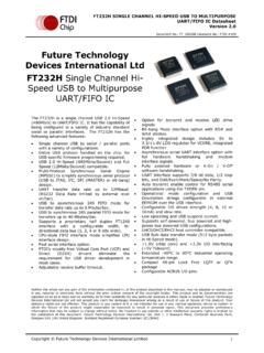
9 Must write 0, read value indeterminatecodeInstruction code, or API function or parameterSection NameSection or Document namexDon t care<Parameter> <> indicate a Parameter is optional or is only used under some conditions{,Parameter}Braces indicate Parameter(s) that repeat one or more times[Parameter]Brackets indicate a nested Parameter. This Parameter is not real and actually decodes into one or more real 6 2010 - 2015 Microchip Technology DIAGRAMFIGURE 2-1:USB251XB/XBI HUB FAMILY BLOCK VUpstream PHYR epeaterControllerSCKSDAPHY# VPLLVDDAVDDCRS erial interface engineSerial interfacePort controllerPort powerUSB datadownstreamPort powerOC senseswitch/ LED driversUSB datadownstreamRouting and port re-ordering V regBus-power detect/Vbus V reg24 MHz crystalUpstream USB dataTo upstreamVBUSTo I2C EEPROM or SMBus masterPHY#xPort #xOC sense switch driver/ LED drivers TT #xTT # #1OC sense switch driver/ LED drivers OC senseswitch/ LED indicates the number of available downstream ports.
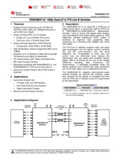
10 2, 3, or 4 2010 - 2015 Microchip Technology 7 USB251 INFORMATIONThis chapter outlines the pinning configurations for each package type available, followed by a corresponding pin listorganized alphabetically. The detailed pin descriptions are listed then outlined by function in Section , "Pin Descrip-tions (Grouped by Function)," on page ConfigurationsThe following figures detail the pinouts of the various USB251xB/xBi 3-1:USB2512B PIN DIAGRAMG round Pad(must be connected to VSS)USB2512B/12Bi(Top View)18NC17161514 VDD3313 CRFILT1211 TEST10 VDDA33 OCS_N2 PRTPWR2/BC_EN2 OCS_N1 PRTPWR1/BC_EN128 VDDA3329 USBDP_UP31 XTALOUT3233 RBIAS36 VDDA3335 PLLFILT34 USBDM_UP30 XTALIN/CLKINSUSP_IND/LOCAL_PWR/NON_REM0 Indicates pins on the bottom of the 8 2010 - 2015 Microchip Technology 3-2:USB2513B PIN DIAGRAMG round Pad(must be connected to VSS)USB2513B/13Bi(Top View)181716151413121110 VDDA33 TESTPRTPWR1/BC_EN1 OCS_N1 CRFILTVDD33 PRTPWR2/BC_EN2 OCS_N2 PRTPWR3/BC_EN3282931323336353430 VDDA33 RBIASPLLFILTXTALIN/CLKINXTALOUTUSBDP_UPU SBDM_UPVDDA33 SUSP_IND/LOCAL_PWR/NON_REM0 Indicates pins on the bottom of the device.