Transcription of USB2000+ Data Sheet - Ocean Optics
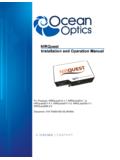
1 usb2000 + data Sheet Description The Ocean Optics usb2000 + Spectrometer includes the linear CCD-array optical bench, plus all the circuits necessary for spectrometer operation. The result is a compact, flexible system, with no moving parts, that's easily integrated as an OEM component. The usb2000 + spectrometer is a unique combination of technologies providing users with both an unusually high spectral response and high optical resolution in a single package. The electronics have been designed for considerable flexibility in connecting to various modules as well as external interfaces. The usb2000 + interfaces to PCs, PLCs and other embedded controllers through USB or RS-232 communications.
2 The information included in this guide provides detailed instructions on the connection and operation of the usb2000 +. The detector used in the usb2000 + spectrometer is a high-sensitivity 2048-element CCD array from Sony, product number ILX511. (For complete details on this detector, visit Sony's web site at Ocean Optics applies a coating to all ILX511 detectors, so the optical sensitivity could vary from that specified in the Sony datasheet). The usb2000 + operates off of a single +5 VDC supply and either a USB or RS-232 interface. The usb2000 + is a microcontroller-controlled spectrometer, thus all operating parameters are implemented through software interfacing to the unit.
3 270-00000-000-05-201603 1. usb2000 + data Sheet A special 500 lines/mm groove density grating option used in the USB2000+ XR spectrometer provides broader spectral coverage with no sacrifice in performance. This extended-range spectrometer is preconfigured with this new grating for general-purpose UV-NIR applications. Features ILX511 Detector High sensitivity detector Readout Rate: Optics An optical resolution of ~ (FWHM). A wide variety of Optics available 14 gratings, plus Grating #31for the XR version 6 slit widths 3 detector coatings 6 optical filters Electrical Performance 16 bit, 3 MHz A/D Converter Integration times from 1ms to 65s 4 triggering modes Embedded microcontroller allows programmatic control of all operating parameters &.
4 Standalone operation USB 480 Mbps (High Speed) & 12 Mbps (Full speed). RS232 115 Kbaud Multiple Communication Standards for digital accessories (SPI, I2C). Onboard Pulse Generator 2 programmable strobe signals for triggering other devices Software control of nearly all pulse parameters Onboard GPIO. 8 user programmable digital I/O. EEPROM storage for Wavelength Calibration Coefficients Linearity Correction Coefficients Absolute Irradiance Calibration (optional). Plug-n-Play Interface for PC applications 22-pin connector for interfacing to external products CE Certification 2 270-00000-000-05-201603. usb2000 + data Sheet Specifications Specifications Criteria Absolute Maximum Ratings: VCC + VDC.
5 Voltage on any pin +4 VDC. Physical Specifications: Physical Dimensions mm x mm x mm Weight 190 g Power: Power requirement (master) 250 mA at +5 VDC. Supply voltage V. Power-up time ~2s depending on code size Spectrometer: Design Asymmetric crossed Czerny-Turner Focal length (input) 42mm Focal length (output) 68mm (75, 83, and 90mm focal lengths are also available). Input Fiber Connector SMA 905. Gratings 14 different gratings, plus Grating #31 for the XR version Entrance Slit 5, 10, 25, 50, 100, or 200 m slits. (Slits are optional. In the absence of a slit, the fiber acts as the entrance slit.). Detector Sony ILX511B CCD.
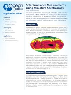
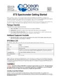
6 Nd rd Filters 2 and 3 order rejection, long pass (optional). Spectroscopic: Integration Time 1 ms 65 sec 8. Dynamic Range 2 x 10 (system), 1300:1 (single acquisition). Signal-to-Noise 250:1 single acquisition Readout Noise (single dark spectrum) 50 counts RMS, 300 counts peak-to-peak Resolution (FWHM) nm varies by configuration (see for configuration options). Spectrometer Channels One Environmental Conditions: Temperature -30 to +70 C Storage & -10 to +50 C Operation Humidity 0% - 90% noncondensing Interfaces: USB USB , 480 Mbps RS-232 2-wire RS-232. 270-00000-000-05-201603 3. usb2000 + data Sheet Mechanical Diagrams Figure 1: usb2000 + Outer Dimensions 4 270-00000-000-05-201603.
7 usb2000 + data Sheet Electrical Pinout Listed below is the pin description for the usb2000 + Accessory Connector located on the front vertical wall of the unit. The connector is a Samtec part # IPT1-111-01-S-D-RA connector. The vertical mate to this is part #IPS1-111-01-S-D-VS and the right angle PCB mount is part #IPS1-111- 01-S-D-RA. Pin# Description Alt Function A1 SPI_CLK. A2 SPICS_OUT. 1 VUSB. 2 Tx 3 Rx 4 LampEnable Pin orientation 5 ContStrobe 6 GND. 20 18 16 14 12 10 8 6 4 2 A2. 7 ExtTrigIn 19 17 15 13 11 9 7 5 3 1 A1. 8 Single Strobe 9 SCL. Looking at Front of usb2000 +. 10 SDA. 11 MOSI. 12 MISO. 13 GPIO-1 (1P)* Master Clock 14 GPIO-0 (2P) Base Clock 15 GPIO-3 (1N) Integration Clock 16 GPIO-2 (2N) Reserved Acquire Spectra 17 GPIO-5 (3P) (Read Enable).
8 18 GPIO-4 (4P) Reserved 19 GPIO-7 (3N) SH CCD pin 20 GPIO-6 (4N) ICG CCD pin Notes: GPIO nP & nN notation is for future LVDS capability 5V Aux pin on the GPIO header is output only 270-00000-000-05-201603 5. usb2000 + data Sheet Function Input/Output Description VCC , VUSB or 5 Vin Input or Output This is the input power pin to the usb2000 +. Additionally when operating via a Universal Serial Bus (USB) this is the USB power connection (+5V) which can be used to power other peripherals (Care must be taken to insure that the peripheral complies with USB Specifications). NOTE: Do not connect both USB power and Auxiliary power (as an input) at the same time.
9 RS232 Tx Output RS232 Transmit signal for communication with PC connect to DB9 pin 2. RS232 Rx Input RS232 Receive signal for communication with PC connect to DB9 pin 3. Lamp Enable Output A TTL signal that is driven Active HIGH when the Lamp Enable command is sent to the usb2000 +. Continuous Output TTL output signal used to pulse a strobe that is divided down from Strobe the Master Clock signal Ground Input/Output Ground Single Strobe Output TTL output pulse used as a strobe signal, which has a programmable delay relative to the beginning of the spectrometer integration period. ExtTrigIn Input The TTL input trigger signal.
10 In External Hardware Trigger mode this is a rising edge trigger input. In Software Trigger Mode this is an Active HIGH Level signal. In External Synchronization Mode (or External hardware Level Trigger Mode) this is a clock input, which defines the integration period of the spectrometer. SCL Input/Output The I2C Clock signal for communications to other I2C peripherals SDA Input/Output The I2C data signal for communications to other I2C peripherals Input/Output 8 General Purpose Software Programmable Digital GPIO(0-7) Inputs/Outputs Output The SPI Master Out Slave In (MOSI) signal for communications to MOSI other SPI peripherals Input The SPI Master In Slave Out (MISO)