Transcription of Vienna Rectifier-Based, Three-Phase Power Factor ...
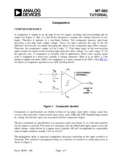
1 Vienna RectifierC2000 MicrocontrollerTMS320F28337xD3 x AMC13013 x UCC21520 DWThree Phase ACFilter3x OPA320DC Output1 xOPA43501xDCH010505SN72x AMC13012x OPA3201xDCH010505SN7V1N2,N,3 NiL1,L2,L3 VBusMNVBusPM1 TIDUCJ0B November2016 RevisedJune2017 SubmitDocumentationFeedbackCopyright 2016 2017,TexasInstrumentsIncorporatedViennaR ectifier-Based,Three-PhasePowerFactorCor rection(PFC)ReferenceDesignUsingC2000 MCUTI Designs:TIDM-1000 ViennaRectifier-Based,Three-PhasePowerFa ctorCorrection(PFC)ReferenceDesignUsingC 2000 MCUD escriptionThe Viennarectifierpowertopologyis usedin high - Power ,three-phasepowerfactorcorrect ionapplicationssuchas offboardelectricvehicle(EV)chargersand therectifiercan be TI Designillustratesamethodto controlthe powerstageusingC2000 microcontroller(MCU).The hardwareand softwareavailablewith this designhelpsacceleratethe time E2E ExpertsFeatures Three-PhaseInput208 VL-L60 Hz, Output600-VDC Nominal, KW Three-PhaseInput400 VL-L50 Hz, Output700-VDC Nominal, KW 50-kHzPulseWidthModulation(PWM)Switching GreaterThan98%PeakEfficiency LessThan2% TotalHarmonicDistortion(THD)atFull Loadand Low Line powerSUITES upportfor EasyAdaptationof theDesignfor UserRequirement SoftwareFrequencyResponseAnalyzer(SFRA)a nd CompensationDesignerfor Easeof TuningofControlLoopsApplications OffboardChargersfor EV TelecomRectifier Drives,Welding,and OtherIndustrialAn IMPORTANTNOTICEat the end of this TI referencedesignaddressesauthorizeduse, intellectualpropertymattersand otherimportantdisclaimersand information.
2 Vdc3PH November2016 RevisedJune2017 SubmitDocumentationFeedbackCopyright 2016 2017,TexasInstrumentsIncorporatedViennaR ectifier-Based,Three-PhasePowerFactorCor rection(PFC)ReferenceDesignUsingC2000 MCU1 SystemDescriptionThree-phasepoweris usedby equipmentoperatingat high powerin improvegrid powerqualityand reducethe harmoniccurrentsdrawn,powerfactorcorrect ionis neededas manyofthe forwardloadsare DC. For example,in an offboard,fast EV charger,operatingat 20 KW, the inputis athree-phaseAC connectionfromthe grid and the outputis DC to the activethree-phasepowerfactorconversion,a Viennarectifieris populardue to its operationin continuousconductionmode(CCM),inherentmu ltilevelswitching(threelevel),andreduced voltagestresson the ,hysteresis-basedcontrollershavebeenused for triangle-basedPWMbeenshownto workfor controlcan be quitechallengingto Viennarectifiersexist,Figure1showsthe variantof the Viennarectifierchosenin this designalongwith the key voltagesand ViennaRectifierVariantImplementedA Y-connectionViennarectifieris implementedin this TI designthe aim is to provideanexampleof how to controla Viennarectifierand how to tunethe differentloopsusingthe C2000 MCU.
3 ! November2016 RevisedJune2017 SubmitDocumentationFeedbackCopyright 2016 2017,TexasInstrumentsIncorporatedViennaR ectifier-Based,Three-PhasePowerFactorCor rection(PFC)ReferenceDesignUsingC2000 SystemLevelSpecificationsThe three-phaseviennarectifierkey powerspecificationare givenin Key SystemSpecificationsPARAMETERSPECIFICATI ONI nputvoltage(Vin) AC 208 VrmsVL-Lor 120 VrmsL-N , 60 Hzor AC 400 VrmsVL-Lor 230 VrmsL-N , 50 HzInputcurrent(Iin)4 AmpsRMSMaxOutputvoltage(Vout) 600-VDC bus nominalat 208 Vrmsor 700-VDC bus nominalat 400 VrmsOutputcurrent(Iout)AbsoluteRMSmaximu m5 Amps,pulsemaximum10 AmpsPowerrating KW at three-phase208 Vrmsor KW at three-phase400 VrmsCurrentTHD <1% at ratedload with 208 Vrms <4% at ratedload with 400 VrmsEfficiencyPeak98%,average~97%Primary filter inductor3 mHOutputcapacitance180 FPWM switchingfrequency50 kHzWARNINGTI intendsthisEVMto be operatedin alabenvironmentonlyanddoesnot considerit to be afinishedproductfor IntendsthisEVMto be usedonlybyqualifiedengineersandtechnicia nsfamiliarwithrisksassociatedwithhandlin ghigh-voltageelectricalandmechanicalcomp onents,systems,and theboard.
4 Theboardoperatesat voltagesandcurrentsthatmaycauseshock,fir e,or injuryif not properlyhandledor the equipmentwithnecessarycautionandappropri atesafeguardsto avoidinjuringyourselfor RectifierC2000 MicrocontrollerTMS320F28337xD3 x AMC13013 x UCC21520 DWThree Phase ACFilter3x OPA320DC Output1 xOPA43501xDCH010505SN72x AMC13012x OPA3201xDCH010505SN7V1N2,N,3 NiL1,L2,L3 VBusMNVBusPM! November2016 RevisedJune2017 SubmitDocumentationFeedbackCopyright 2016 2017,TexasInstrumentsIncorporatedViennaR ectifier-Based,Three-PhasePowerFactorCor rection(PFC)ReferenceDesignUsingC2000 MCUCAUTIONDo not !Thereareaccessiblehighvoltagespresenton the board. Electricshockis boardoperatesatvoltagesand currentsthat may causeshock,fire, or injuryif the equipmentwith necessarycautionand appropriatesafeguardsto safety,use of isolatedtest equipmentwith overvoltageand overcurrentprotectionis considersit the user's responsibilityto confirmthat thevoltagesand isolationrequirementsare identifiedandunderstoodbeforeenergizingt he boardor ,do not touchthe EVMor componentsconnectedto the surface!
5 Not touch!Somecomponentsmay reachhigh temperatures>55 C whenthe boardis poweredon. The usermustnot touchthe boardatany pointduringoperationor immediatelyafteroperating,ashigh temperaturesmay be showsthe blockdiagramof the Viennarectifierchosenin this designalongwith the key voltagesand November2016 RevisedJune2017 SubmitDocumentationFeedbackCopyright 2016 2017,TexasInstrumentsIncorporatedViennaR ectifier-Based,Three-PhasePowerFactorCor rection(PFC)ReferenceDesignUsingC2000 MCUF2837xThe C2000 MCUsare an optimizedMCUfamilyfor fast and high -qualityanalog-to-digitalcontrollere nablesaccuratemeasurementof the currentand voltagesignals,andthe integratedcomparatorsubsystem(CMPSS)inte gratesprotectionfor overcurrentand overvoltagewithoutuse of any optimizedCPUcoreenablesfast executionof acceleratedusingthe on-chiptrigonometricmathunit (TMU)
6 ,whichimpartsadditionalspeedupin controlloop UCC21520is an isolated,dual-channelgatedriverwith a 4-A sourceand a 6-A sink driveris designedto drivepowerMOSFETs,IGBTs,and SiC MOSFETsup to 5 MHzwith a best-in-classpropagationdelayand inputside is isolatedfromthe two outputdriversby a ,with a minimumof 100-V/nscommon-modetransientimmunity(CMT I).Internalfunctionalisolationbetweenthe two secondary-sidedriversallowsa workingvoltageof up to 1500-VDC. A disablepin shutsdownbothoutputssimultaneouslywhense t high andallowsnormaloperationwhenleft floatingor deviceacceptsVDDsupplyvoltagesup to 25V. A wideinputVCCI rangefrom3 to 18 V makesthe driversuitablefor interfacingwith AMC1301is a precisionisolationamplifierwith an outputseparatedfromthe inputcircuitryby anisolationbarrierthat is highlyresistantto inputof the AMC1301is optimizedfordirectconnectionto shuntresistorsor otherlow OPA320is a precision,low- Power ,single-supplyop ampoptimizedfor to V, the deviceis well-suitedfor drivinganalog-to-digitalconverters(ADCs) .
7 Witha typicaloffsetvoltageof 40 V and very-lowdrift overtemperature( V/ C typical),it is very wellsuitedfor applicationslike controlloop and currentsensingin Q1 Q2 MVbus/2 D = duty commanded from the control loopZROCLRCAUSETCADTGLZROCLRPWM ModulatorGate November2016 RevisedJune2017 SubmitDocumentationFeedbackCopyright 2016 2017,TexasInstrumentsIncorporatedViennaR ectifier-Based,Three-PhasePowerFactorCor rection(PFC)ReferenceDesignUsingC2000 MCU3 ControlSystemDesignTheoryThis sectiondiscussesthe SinglePhaseDiagramof ViennaRectifierFigure3 showsa simplified,single-phasediagramof the controlthis rectifier,the dutycycleis controlledsuchthat it regulatesthe , if the softwarevariableDutyis setto 1, it makesvxiNthe largestvoltagepossibleby neverturningon Q1 and Q2 switchesand lettingtheinductorconnectto the DC bus thoughthe set to 0, PWMismodulatedsuchthat Q1 and Q2 alwaysconductmakingvxiNconnectto the midpointof the DC bus (whichis zero),whichmakesit the lowestpossiblevoltagefor the CMPA will become effective here1234 ADC SOCCAUSETCADTGLISRZROCLRW rites to PWM will happen somewhere here CAUSETCADTGLZROCLRQ2Q1(Note Action Qualifiers are not shadow loaded)
8 1343 Positive HalfNegative Half2121 CAUSETCADTGL43 CAUSETCADTGLZROCLR Q1 Q2 MLi Q1 Q2 MLi Q1 Q2 MLi Q1 November2016 RevisedJune2017 SubmitDocumentationFeedbackCopyright 2016 2017,TexasInstrumentsIncorporatedViennaR ectifier-Based,Three-PhasePowerFactorCor rection(PFC)ReferenceDesignUsingC2000 MCUD etailedPWMconfigurationis shownin ViennaRectifierDetailedPWMM odulationSchemeLbusDCL o R Vi1 sR C NrmsDCbusNrms NrmsDCLibusV iv3nvii3niV +-Gi--+++Ki_gainINV _gainVKu[busv _ gain1VK2ubusV2i LiuDGdiLiRii1sLVINVxINKi_fltrKi_gainLip _ ii _ gaini _ fltrdv _ gainii11 HKKGDKZ busxiNVVD2 November2016 RevisedJune2017 SubmitDocumentationFeedbackCopyright 2016 2017,TexasInstrumentsIncorporatedViennaR ectifier-Based,Three-PhasePowerFactorCor rection(PFC)ReferenceDesignUsingC2000 understandthe currentloop model,first look at the Figure3 the duty cycleD is providedto the PWMmodulator,whichis connectedto the switchesQ1 and Q2.]
9 Withthis in mind,see Equation1:(1)NOTE:WhenD is set to 1, all the switchesareoff, and whenD is 0, all switchesareon, whichconnectthe inductorto the pointto modulatethe currentthroughthe inductor,the voltagevxiNis regulatedusingthe duty cyclecontrolofQ1 and Q2 directionof currentis positivein the directionfromthe AC line into therectifierand usingthe DC bus feedforward,the inputAC voltagefeedforwardalongwith the assumptionthat the grid is fairlystiff. The currentloop can be simplifiedas shownin Figure5, and the currentloopplantmodelcan be writtenas in Equation2.(2)Figure5. CurrentLoopControlModelNOTE:The negativesign on the referenceis in placebecausethe currentloop is thoughtto beregulatingthe voltagevxiN. To increasethe current,vxiNmustbe reducedand,thus,theoppositesign for referenceand feedbackin Figure5.
10 This currentloop modelis usedto tunethe simpleproportionalcontrolleris usedfor the of the proportionalgain is adjustedto ensurethe systemis Bus RegulationLoopThe DC bus regulationloop is assumedto be providingthe loop is dividedby thesquareof the line voltagesRMSto providethe conductance,whichis furthermultipliedby the line voltageto give the the DC bus regulationloop is developedby linearizingEquation3 aroundtheoperatingpoint.(3)For resistiveload the bus voltageand currentrelate,as shownin Equation4.(4)s _ outbus _ PMbus _ MNs _ gain _ KpG(VV) G UvUmaxK2 EvE1K1E2 Umin = 0Kp = K1, for E(n)<E1 and E(n)>E2Kp = K2, for E(n)<E1 and E(n)>E2+-[GbusKv_gain+-Ki_gainKv_fltrKv_gaina cv _ gainvKu*busv22Nv _ fbk13 VKu*PO*iLiVbus_avgKv_gain*i p i p G G 1 G G rmsbusV3 VKLL o R1 sR C iDCVbus^^p _ busloadi _ gainv _ gainv _ fltHHN KKK November2016 RevisedJune2017 SubmitDocumentationFeedbackCopyright 2016 2017,TexasInstrumentsIncorporatedViennaR ectifier-Based,Three-PhasePowerFactorCor rection(PFC)ReferenceDesignUsingC2000 MCUThe DC voltageregulationloop controlmodelcan be drawn,as shownin Figure6.]