
HSPICE User Guide: Simulation and Analysis
HSPICE® User Guide: Simulation and Analysis Version B-2008.09, September 2008
Download HSPICE User Guide: Simulation and Analysis

Information
Domain:
Source:
Link to this page:
Documents from same domain
Diodes and Transistors
inst.eecs.berkeley.eduDiodes and Transistors 1. ... basic semiconductor physics. We won’t discuss the details because the point of this ... switch. Below the specified ...
HSPICE Tutorial - University of California, Berkeley
inst.eecs.berkeley.eduHSPICE Tutorial Contents 1 Introduction 1 ... ee105 spice tutorial example 1 - simple rc circuit in the Results Browser and double-clicking vs and vo to plot them in the graph. You may have been able to guess from the netlist, but you’ll see that vsis a …
Introduction to LabVIEW - University of California, …
inst.eecs.berkeley.eduIntroduction to LabVIEW 1. Introduction Welcome to the LabVIEW component of EE100! This lab is just a simple introduction to the graphical circuit simulation ...
Introduction to LabVIEW For Use in Embedded …
inst.eecs.berkeley.eduUC Berkeley EE249 Hugo.Andrade@ni.com Introduction to LabVIEW For Use in Embedded System Development
EE105 –Fall 2015 Microelectronic Devices and Circuits
inst.eecs.berkeley.eduSummary of MOS Single-Transistor Amplifiers MOS Common Source Common Source with Deg. Common Drain Common Gate Ri ∞ ∞ ∞ Small Ro Large Very Large Small Large
Introduction to Digital Systems - University of …
inst.eecs.berkeley.eduDepartment of EECS EE100/42-43 Spring 2007 Rev. 1 Introduction to Digital Systems 0. Acknowledgments Many thanks to Prof. Bernhard Boser and National Instruments for funding this project in the
EE126: Probability and Random Processes - Lecture 1 ...
inst.eecs.berkeley.eduprobability 4 The probabilities summed over all of the base outcomes always equals 1 Example: Toss a fair coin twice 1 Base outcomes are HH,HT,TH,TT 2 This covers all the possibilities. M.E. 3 Each of these outcomes is equally likely 4 Assign each outcome a probability of 0:25. The list (set) of base outcomes is called the Sample Space.
EECS 126 Probability and Random Processes: Course Syllabus ...
inst.eecs.berkeley.eduDescription: Probability is a mathematical discipline that allows one to reason about uncertainty: it helps us to predict uncertain events, to make better decisions under uncertainty, and to design and build systems. Throughout the course, we will teach you the fundamental ideas of probability and random processes along with the labs.
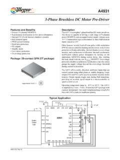
3-Phase Brushless DC Motor Pre-Driver
inst.eecs.berkeley.eduDescription The A4931 is a complete 3-phase brushless DC motor pre-driver . The device is capable of driving a wide range of N-channel power MOSFETs and can support motor supply voltages up to
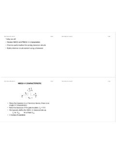
DS -V I G - EECS Instructional Support Group Home Page
inst.eecs.berkeley.eduG D S I D I G-V DS + + V G S _ NMOS I-V CHARACTERISTIC • Since the transistor is a 3-terminal device, there is no single I-V characteristic. • Note that because of the gate insulator, I G = 0 A. • We typically define the MOS I-V characteristic as I D vs. V DS for a fixed V GS. • 3 modes of operation
Related documents

Mathematical Programming: An Overview 1
web.mit.eduSimulation Simulation models are similar to gaming models except that all human decision-makers are removed from the modeling process. The model provides the means to evaluate the performance of a number of alterna-tives, supplied externally to the model by the decision-maker, without allowing for human interactions at
RF Power Amplifier Design
www.rfsilicon.comAmplifier Design – Simulation ~Dynamic Load Line & Power Sweep 0 3 6 9 12 15 Voltage (V) Dynamic load line-2000 0 2000 4000 6000 8000 IVCurve (mA) IV_Curve Dynamic Load Line (mA) Amp 0 5 10 15 20 24 Power (dBm) Power Sweep 1 Tone 0 10 20 30 40 0 10 20 30 40 50 60 70 80 Output Power (L, dBm) Amp PAE (R) Amp

HSPICE Quick Reference Guide
www2.ece.rochester.eduHSPICE Simulation and Analysis User Guide. Behavioral Voltage Source See “Voltage and Current Controlled Elements” in the HSPICE Simulation and Analysis User Guide. Ideal Op-Amp See “Ideal Op-Amp” in the HSPICE Simulation and Analysis User Guide. Ideal Transformer See “Ideal Transformer” in the HSPICE Simulation and Analysis User Guide.

IBIS MODELING COOKBOOK For IBIS Version 4
ibis.organ executable simulation model – it is a standard for the formatting and transfer of data. As such, the specification defines what the information included in an IBIS file represents and how it is to be gathered. It does not specify what an analog simulation application does with the data. IBIS models are component-centric.

Design method for two-Stage CMOS operational amplifier ...
mpra.ub.uni-muenchen.de2. System Design and Modeling 2.1. Operational Amplifier Compensation Typical two-stage Op-amp (Figure 1) can be illustrated as the following diagram [28]: Figure 3. Typical two-stage Op-amp According to Figure 4, the 1st stage is a differential amplifier, and the gain and pole frequency of this stage can be calculated by Eq. (1).
CMOS Analog Circuit Design
picture.iczhiku.comare presented so that the reader can appreciate computer simulation models. Other models for the subthreshold operation are presented along with how to use SPICE for computer simula-tion of MOSFET circuits. Chapters 4 and 5 present the topics of subcircuits and amplifiers that will be used to design more complex analog circuits, such as an op amp.

OWNER’S MANUAL - Fractal Audio Systems - Amp Modeling ...
www.fractalaudio.comown amp, speaker cab, and effects. The AX8 features over 222 “Quantum” amp models utilizing the same technology as our flagship Axe-Fx II. Ultra-Res™ Speaker Cab simulation provides a level of accuracy that only Fractal Audio Systems can offer. AX8 is also compatible with our entire library of Cab-Packs.