Introduction to RF Simulation and its Application
communication systems [1,16,47,48]. In this architecture the RF input signal is directly converted to baseband in one step. Thus, most of the gain will be at baseband and the LO will be at the same frequency as the input signal. In this case, the ability to deter-mine the impact of small amou nts of coupling is quite important and will require ...
Download Introduction to RF Simulation and its Application

Information
Domain:
Source:
Link to this page:
Documents from same domain
Predicting the Phase Noise and Jitter of PLL-Based ...
designers-guide.orgPredicting the Phase Noise and Jitter of PLL-Based Frequency Synthesizers Introduction 4 of 52 The Designer’s Guide Community www.designers-guide.org also rules out any PLL that is implemented wi th a phase detector that has a dead zone. A dead zone has the effect of opening the loop and letting the phase drift seemingly at ran-

Power Supply Noise Reduction - Designer’s Guide
designers-guide.orgMar 10, 2019 · Power Supply Noise Reduction Introduction 2 of 12 The Designer’s Guide Community www.designers-guide.org 1 Introduction Many of the problems that appear out of Mu rphy’s box upon transforming a design from the mythical world of textbooks and S PICE to the real world eman ate from the non-ideal power supply.
JEDEC STANDARD - Designer’s Guide
designers-guide.orgJ-STD-020, Joint IPC/JEDEC Standard, Moisture/Reflow Sensitivity Classification for Nonhermetic Solid State Surface-Mount Devices. JP-001, Foundry Process Qualification Guidelines (Wafer Fabrication Manufacturing Sites). JESD22 Series, Reliability Test Methods for Packaged Devices
A Test Bench for Differential Circuits - Designer’s Guide
designers-guide.orgA Test Bench for Differential Circuits The New Test Bench 4 of 7 The Designer’s Guide Community www.designers-guide.org Notice that In these equations, ip and in defy normal convention and are positive as they exit their pins so that the current at one side of the balun matches the direction at the
Simulating Switched-Capacitor Filters with SpectreRF
designers-guide.orgSimulating Switched-Capacitor Filters with SpectreRF A Simple Track and Hold 4 of 25 The Designer’s Guide Community www.designers-guide.org (freq2 = 10.1kHz ampl2 = 0 fundname2 = “input2”).Initially, the waveshape is set to a fixed value by type = dc.Later, the alter statement named enableTone1 changes the waveshape type to sine to enable the first tone.

Random Offset in CMOS IC Design - Designer’s Guide
designers-guide.orgOct 19, 2007 · Random Offset in CMOS IC Design ECEN4827/5827 Analog IC Design October 19, 2007 Art Zirger, National Semiconductor art.zirger@nsc.com 303-845-4024
Design of MOS Amplifiers Using gm/ID Methodology
designers-guide.orgWhy gm/Id Methodology The choice of gm/Id is based on its relevance for the three following reasons: 1. It is strongly related to the performances of analog circuits. 2. It gives an indication of device operating region. 3. It provides a tool for calculating the transistors dimensions.
Related documents
Understanding How Ferrites Can Prevent and Eliminate RF ...
audiosystemsgroup.comUnderstanding How Ferrites Can Prevent and Eliminate RF Interference to Audio Systems Page 4 Fig 11 – Series reactive component of the chokes of Fig 8 The difference between these materials that accounts for this behavior is their chemical composition (i.e., their mix)! #78 is a MnZn ferrite, while #43 and #61 are NiZn ferrites.

RF, Microwave, and Millimeter Wave Products
www.analog.comA unique combination of design skills. Deep systems know-how. A diverse range of process technologies including GaAs, GaN, SiGe, SOI, and CMOS. That’s the difference behind the industry’s broadest portfolio of RF ICs, covering the entire RF signal chain from bits to beams, and from DC to beyond 100 GHz. With over 1000 high performance
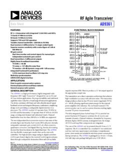
RF Agile Transceiver Data Sheet AD9361 - Analog Devices
www.analog.comThe AD9361 is a high performance, highly integrated radio frequency (RF) Agile Transceiver™ designed for use in 3G and 4G base station applications. Its programmability and wideband ... division duplex (FDD) systems, is integrated into the design. All VCO and loop filter components are integrated. The core of the AD9361 can be powered ...

Understanding the RF path - CommScope
www.commscope.comRF systems, then and now Wireless communication is a mature science. RF systems have been in commercial use since the 1940s, with the earliest examples including community repeaters, paging systems, point-to-point links and specialized mobile radio (trunked) systems. More recent innovations and uses of the RF spectrum
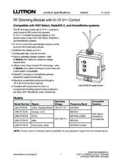
RF Dimming Module with 0–10 V Control SPEC (369806)
www.lutron.comThe RF dimming module with 0–10 V- control is a radio frequency (RF) control that operates 0–10 V- controlled fluorescent ballasts or LED drivers based on input from RA2 Select, RadioRA 2, and HomeWorks systems. • 0–10 V- control link automatically sources or sinks up to 60 mA to third-party fixtures. • Switches line voltage up to 5 A.

Phase-Locked Loop Design Fundamentals - NXP
www.nxp.comSimilarly, applying the three inputs in to type 1, 2, and 3 systems and util izing the final value theorem, the following table can be constructed showing the respective steady state phase errors. Table 1. Steady State Phase Errors for Various System Types Type 1 Type 2 Type 3 Step Position Zero Zero Zero Step Velocity Constant Zero Zero
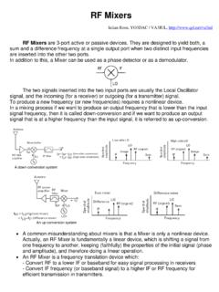
RF Mixers - QSL.net
www.qsl.net- LO component in the RF input can pass back through the mixer and be modulated by the LO signal, and a DC and 2fo components are created at the IF output. - This has no consequence for a heterodyne system, but can cause problems for homodyne systems (i.e., zero IF) • LO to RF port isolation is by far the biggest short coming 5.
RF Basics, RF for Non-RF Engineers - Texas Instruments
www.ti.comRF Communication Systems • Half-duplex RF Systems Operation mode of a radio communication system in which each end can transmit and receive, but not simultaneously. Note: The communication is bidirectional over the same frequency, but unidirectional for the duration of a message. The devices need to be transceivers. Applies to most TDD and ...