
Sequential Logic Implementation
Finite state machines and their state diagrams Inputs/outputs Mealy, Moore, and synchronous Mealy machines Finite state machine design procedure Verilog specification Deriving state diagram Deriving state transition table Determining next state and output functions Implementing combinational logic
Download Sequential Logic Implementation

Information
Domain:
Source:
Link to this page:
Documents from same domain

Diodes and Transistors
inst.eecs.berkeley.eduDiodes and Transistors 1. ... basic semiconductor physics. We won’t discuss the details because the point of this ... switch. Below the specified ...
HSPICE Tutorial - University of California, Berkeley
inst.eecs.berkeley.eduHSPICE Tutorial Contents 1 Introduction 1 ... ee105 spice tutorial example 1 - simple rc circuit in the Results Browser and double-clicking vs and vo to plot them in the graph. You may have been able to guess from the netlist, but you’ll see that vsis a …
Introduction to LabVIEW - University of California, …
inst.eecs.berkeley.eduIntroduction to LabVIEW 1. Introduction Welcome to the LabVIEW component of EE100! This lab is just a simple introduction to the graphical circuit simulation ...

Introduction to LabVIEW For Use in Embedded …
inst.eecs.berkeley.eduUC Berkeley EE249 Hugo.Andrade@ni.com Introduction to LabVIEW For Use in Embedded System Development

EE105 –Fall 2015 Microelectronic Devices and Circuits
inst.eecs.berkeley.eduSummary of MOS Single-Transistor Amplifiers MOS Common Source Common Source with Deg. Common Drain Common Gate Ri ∞ ∞ ∞ Small Ro Large Very Large Small Large
Introduction to Digital Systems - University of …
inst.eecs.berkeley.eduDepartment of EECS EE100/42-43 Spring 2007 Rev. 1 Introduction to Digital Systems 0. Acknowledgments Many thanks to Prof. Bernhard Boser and National Instruments for funding this project in the

EE126: Probability and Random Processes - Lecture 1 ...
inst.eecs.berkeley.eduprobability 4 The probabilities summed over all of the base outcomes always equals 1 Example: Toss a fair coin twice 1 Base outcomes are HH,HT,TH,TT 2 This covers all the possibilities. M.E. 3 Each of these outcomes is equally likely 4 Assign each outcome a probability of 0:25. The list (set) of base outcomes is called the Sample Space.

EECS 126 Probability and Random Processes: Course Syllabus ...
inst.eecs.berkeley.eduDescription: Probability is a mathematical discipline that allows one to reason about uncertainty: it helps us to predict uncertain events, to make better decisions under uncertainty, and to design and build systems. Throughout the course, we will teach you the fundamental ideas of probability and random processes along with the labs.

3-Phase Brushless DC Motor Pre-Driver
inst.eecs.berkeley.eduDescription The A4931 is a complete 3-phase brushless DC motor pre-driver . The device is capable of driving a wide range of N-channel power MOSFETs and can support motor supply voltages up to
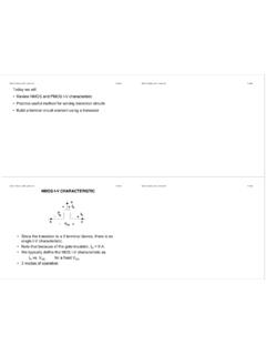
DS -V I G - EECS Instructional Support Group Home Page
inst.eecs.berkeley.eduG D S I D I G-V DS + + V G S _ NMOS I-V CHARACTERISTIC • Since the transistor is a 3-terminal device, there is no single I-V characteristic. • Note that because of the gate insulator, I G = 0 A. • We typically define the MOS I-V characteristic as I D vs. V DS for a fixed V GS. • 3 modes of operation
Related documents
Basic Verilog
euler.ecs.umass.eduFinite State Machines - 2 State diagrams are representations of Finite State Machines (FSM) Mealy FSM Output depends on input and state Output is not synchronized with clock »can have temporarily unstable output Moore FSM Output depends only on state Mealy FSM Moore FSM ECE 232 Verilog tutorial 26 Example 1: Sequence Detector Circuit ...

Example finite state machine - Princeton University
www.cs.princeton.eduHow To Design A Finite State Machine Here is an example of a designing a finite state machine, worked out from start to finish. Step 1: Describe the machine in words. In this example, we’ll be designing a controller for an elevator. The elevator can be at one of two floors: Ground or First. There is one button that controls the elevator, and ...

Finite-State Machine (FSM) Design
digitalsystemdesign.inFinite-State Machine (FSM) Design FSMs, an important category of sequential circuits, are used frequently in designing digital systems. From the daily used electronic machines to the complex digital systems, FSMs are used everywhere. For example, in a station the vending machine which dispatches ticket uses a simple FSM.

EECS150: Finite State Machines in Verilog
inst.eecs.berkeley.eduan example use-case for the Moore machine FSM template. The FSM shown in Figure 1 is useful because it exemplifies the following: 1. The concept of an initial state.1 2. States with non-conditional outward transitions. 3. States with conditional outward transitions. 1There must always be an initial state for the FSM to start at after a Reset. 1

Appendix A. Verilog Code of Design Examples
link.springer.comAppendix A. Verilog Code of Design Examples The next pages contain the Verilog 1364-2001 code of all design examples. The old style Verilog 1364-1995 code can be found in [441].

Finite State Machines - Massachusetts Institute of …
web.mit.edu• State transition diagramis a useful FSM representation and design aid: Step 1: State Transition Diagram • Block diagram of desired system: DQ Level to Pulse FSM LP unsynchronized user input Synchronizer Edge Detector This is the output that results from this state. (Moore or Mealy?) 11 Binary values of states “if L=0 at the clock edge ...

The LC3 Datapath (Chapter 5, Appendix B,C)
cs2461-2020.github.iomodeled as a finite state machine •The control unit is a state machine •Transition from state to state based on the steps in the instruction cycle, the opcode, and outcome (for branches) oDetermine the signals to be generated at each phase of the instruction cycle –these are the outputs to be generated by the FSM •Appendix C has ...

Integrated Metrics Center Technical Brief
www.cadence.comcoverage—block, expression, toggle, and finite state machine (FSM)—as well as assertion and functional coverage. An activity center consists of a coverage metrics window, a source code window, an attributes window, and often, depending on the type of metric, an additional deep-dive analysis window. The

Vitis High-Level Synthesis User Guide
www.xilinx.comControl logic extraction creates a finite state machine (FSM) that sequences the operations in the RTL design according to the defined schedule. S c h e d u l i n g a n d B i n d i n g E x a m p l e