SiC Power Devices and Modues Application Note
breakdown voltage power devices from 600 V to several thousand V can be manufactured with a drift layer having a higher impurity concentration and a thinner thickness compared with Si devices. Most of the resistance component of high breakdown voltage power devices is the resistance of this drift layer.
Download SiC Power Devices and Modues Application Note

Information
Domain:
Source:
Link to this page:
Documents from same domain
Linear Regulator IC Series Linear Regulator 기초
fscdn.rohm.comLinear Regulator 는 기본적으로 입력, 출력, GND 핀으로 구성되며, 출력이 가변일 경우는 출력전압의 귀환이 필요 하기 때문에 귀환(Feedback)핀이 추가됩니다. (Figure 1) IN OUT FB GND V IN V O Figure 1. Linear Regulator 의 기본구성 Linear Regulator 내부회로의 개요는 Figure 2 …
Op-Amp/Comparator Application Note - Rohm
fscdn.rohm.comop-amp. Generally, an op-amp is composed of three stages: the input stage, the gain stage, and the output stage. The input stage is configured with a differential amplification stage that amplifies the differential voltage between the two terminals. In addition, it does not amplify the common-mode signal component (a condition where no ...
Efficiency of Buck Converter
fscdn.rohm.comEfficiency of Buck Converter Switching regulators are known as being highly efficient power sources. To further improve their efficiency, it is helpful to understand the basic mechanism of power loss. This application note explains power loss factors and methods for calculating them.
Snubber Circuit for Buck Converter IC : Power Management
fscdn.rohm.comSnubber Circuit for Buck Converter IC AEK59-D1-0311-0 For example, when the input voltage VIN is 24 V and the switching frequency fSW is 1 MHz, 2 Ë Ì Ç » L680 pF H24 6 H1 MHz L0.39 W the generated consumption power of 0.39 W requires a 6432 size resistor (2512 in inches) with a rated power of 1 W.
ISO 26262: Functional Safety Standard for Modern Road …
fscdn.rohm.comIntrinsic safety is a method for ensuring safety by removing the causes of danger. Functional safety, on the other hand, is a method of reducing risks to an acceptable level to ensure safety ... verification, prototyping, and evaluation are clarified, with reviews performed at each stage. It is also necessary to manage the documents created at
Calculation of Power Loss (Synchronous) : Power Management
fscdn.rohm.comCalculation of Power Loss (Synchronous) This application note describes how to obtain the power loss required to calculate the temperature of a semiconductor device. Temperature control is important to ensuring product reliability. Figure 1 is a circuit diagram of a synchronous rectification type DC/DC converter. Figure 2 shows a switching node ...
Inductor Calculation for Buck Converter IC
fscdn.rohm.comInductor Calculation of Buck Converter Current-difference between max. and min. (ILP-ILT) is as follows: IN SW D SW IN SW OUT D OUT LP LT V V V L f V V V V V I I (15) Equations (13) and (15) show that large inductance L and high switching frequency will reduce maximum current (ILP)and current difference between max. and min. (ILP-ILT).
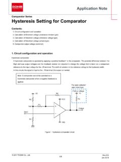
Hysteresis Setting for Comparator - Rohm
fscdn.rohm.comprovided only to illustrate the standard usage and operations of the Products. The peripheral conditions must be taken into account when designing circuits for mass production. The technical information specified herein is intended only to show the typical functions of and examples of application circuits for the Products.
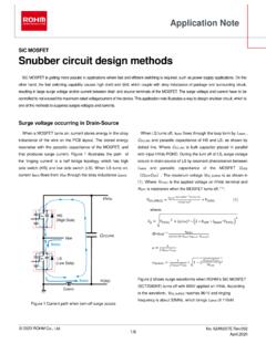
Snubber circuit design methods - Rohm
fscdn.rohm.comis bulk capacitor placed in parallel with input HVdc-PGND. During the turn off of LS, surge voltage occurs in drain-source of LS by resonant phenomenon between L MAIN and parasitic capacitance of the MOSFET C OSS ( C DS + DG). The maximum voltage V DS_SURGE is as shown in (1). Where V HVDC is the applied voltage on HVdc terminal and R OFF

ROHM Switching Regulator Solutions Synchronous Buck ...
fscdn.rohm.comROHM Switching Regulator Solutions Synchronous Buck Converter Controller BD9611MUV-EVK-001 Description Using a synchronous rectified step-down DC/DC converter IC BD9611MUV BD 9611MUV-EVK-001 evaluation board 15.0 V ~ output a 24 V input voltage 12.0 V. Provides 10.0A output current. Output current is possible with current settings by selecting
Related documents

Overview of Mitsubishi Services
www.mitsubishi-motors.comThe drive belt (including fan belt, power steering belt, A/C belt) is a consumable part that is very important to the efficient operation of engine accessory components such as the alternator, power steering, air conditioner, engine cooling system etc. In the worst case of a …

LT1028/LT1128 - Ultralow Noise Precision High Speed Op Amps
www.analog.comVOS Input Offset Voltage (Note 2) 10 40 20 80 µV ∆VOS ∆Time Long Term Input Offset Voltage Stability (Note 3) 0.3 0.3 µV/Mo IOS Input Offset Current VCM = 0V 12 50 18 100 nA IB Input Bias Current VCM = 0V ±25 ±90 ±30 ±180 nA en Input Noise Voltage 0.1Hz to 10Hz (Note 4) 35 75 35 90 nVP-P Input Noise Voltage Density fO = 10Hz (Note 5)

Automotive Circuit Protection using Littelfuse Automotive ...
m.littelfuse.comwhile the rest are surface mount. These devices help the power system pass the different surge tests (1, 2a, 2b, 3a, 3b, 5a and 5b) operationally as specified by ISO7637-2. Referred to the table 12 volt system below, only if the alternator Ri value is higher than 4.5Ω, TPSMD series TVS can then be used to pass the higher energy 5a surge.

DS3231 Etremel Accrate I 2CInterate RTCTCXOCrstal
datasheets.maximintegrated.comActive Supply Current ICCA (Notes 4, 5) VCC = 3.63V 200 µA VCC = 5.5V 300 Standby Supply Current ICCS I2C bus inactive, 32kHz output on, SQW output off (Note 5) VCC = 3.63V 110 µA VCC = 5.5V 170 Temperature Conversion Current ICCSCONV I2C bus inactive, 32kHz output on, SQW output off VCC = 3.63V 575 µA VCC = 5.5V 650 Power-Fail Voltage VPF 2 ...

Course Notes - College of Engineering
engineering.purdue.eduelectrical power grid, the state of a computer system, etc. The presence of dy-namics implies that the behavior of the system cannot be entirely arbitrary; the temporal behavior of the system’s state and outputs can be predicted to some extent by an appropriate model of the system. Example 1.1. Consider a simple model of a car in motion.