
VOLTAGE TRANSFORMERS
watts at rated secondary voltage when rated phase-to-ground voltage is impressed across the capacitance voltage divider. The rated burden of the device is the sum of the watt burdens that may be impressed on both secondary windings simultaneously. Adjustment capacitors are provided in the device for connecting in parallel with the
Download VOLTAGE TRANSFORMERS

Information
Domain:
Source:
Link to this page:
Documents from same domain

DIGITAL CONTROL SYSTEM PRODUCT SOLUTIONS …
www.gegridsolutions.comUnlock the value of your substation data with Alstom™s multi-function substation server DIGITAL CONTROL SYSTEM PRODUCT SOLUTIONS DAPserver Multi-function substation server
Fundamentals of a Motor Thermal Model and its …
www.gegridsolutions.comMotor Thermal Model Protection Applications 41 1. Abstract This paper discusses the fundamentals of a motor thermal model and its mathematical interpretation and physics for the
ANSI Standard Device Numbers & Common …
www.gegridsolutions.comGEDigitalEnergycom 1 ANSI Standard Device Numbers & Common Acronyms Suffixes Description _1 Positive-Sequence _2 Negative-Sequence A Alarm, Auxiliary Power AC Alternating Current ...
Instrument Transformer Basic Technical …
www.gegridsolutions.comg ITI Digital Energy Instrument Transformer Basic Technical Information and Application
MiCOM P543, P544, P545, P546 - GE Grid Solutions
www.gegridsolutions.comMiCOM P543, P544, P545, P546 Technical Manual Current Differential Relays Platform Hardware Version: K Platform Software Version: …
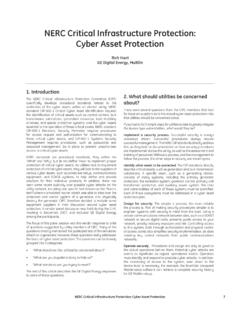
NERC Critical Infrastructure Protection: Cyber Asset ...
www.gegridsolutions.comNERC Critical Infrastructure Protection: Cyber Asset Protection. 7. 1. Introduction. The NERC Critical Infrastructure Protection Committee (CIPC)

469 Motor Management Relay - GE Grid Solutions
www.gegridsolutions.comtoc table of contents 469 motor management relay – instruction manual toc–i table of contents 1: getting started important procedures ..... 1-1

GCCIA Phase 1 - GE Grid Solutions
www.gegridsolutions.comThe GCCIA is an organisation formed in July 2001 in order to create an integrated and sustainable energy economy amongst the six Gulf States. MakinG interconnection in the Gulf a reality GCCIA Phase 1
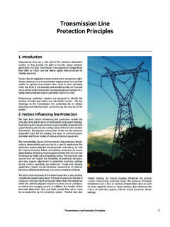
Transmission Line Protection Principles - GE Grid …
www.gegridsolutions.comTransmission Line Protection Principles 7 1. Introduction Transmission lines are a vital part of the electrical distribution system, as they provide the …
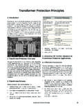
Transformer Protection Principles - GE Grid Solutions
www.gegridsolutions.comTransformer Protection Principles 47 phase shift of the protected transformer. Traditional installations may use delta-connected or wye-connected CTs that externally
Related documents

Lecture 20 Bipolar Junction Transistors (BJT): Part 4 ...
alan.ece.gatech.edu•Warning: Just like when a diode voltage exceeds a certain value, the non-linear behavior of the diode leads to distortion of the current/voltage curves (see previous lecture), if the inputs/outputs exceed certain limits, the full Ebers -Moll model ... Applying a voltage divider: BE /v.
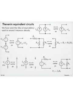
Thevenin equivalent circuits - Iowa State University
tuttle.merc.iastate.eduJun 10, 2014 · The open-circuit voltage / short-circuit current approach can be used to calculate the Thevenin equivalent for a known circuit. Consider the circuit from slide 4: + – V S R 1 R 2 I S 9V 6 mA 1.5 k! 3 k! Open-circuit voltage – Use whatever method you prefer. We’ll use node voltage in this case. + – V S R 1 R 2 I S v a + – v oc YRF= YD ...
Solving circuits directly using Laplace
tuttle.merc.iastate.eduvoltage divider. = 1 sC R+ 1 sC +sL V i (s) V C (s) = Z C Z R +Z C +Z L V i (s) V C (s) = (1 1+sRC+s2LC)(V f s) = V f LC s(s2 +s R L + 1 LC) – + + – Z R V i (s) Z C V C (s) Z L Convert to the frequency domain. Z R = R

Lecture 19 - MIT
web.mit.eduVoltage divider at input: Voltage divider at output: Loaded voltage gain: v in=R vs Rin +Rs vout =RL Avovin Rout +RL vout vs = Rin Rin +RS Avo RL RL +Rout +-vin +-Avovin vout Rout +-Rin Rs vs +-RL unloaded circuit output loading input loading. 6.012 Spring 2007 Lecture 19 8 Small-signal voltage gain Avo: draw small-signal

Chapter 6: Voltage Regulator - Ajlon Tech
www.ajlontech.comA feedback voltage obtained from voltage divider R 1 and R 2 is applied to the op-amp’s non-inverting input and compared to the Zener voltage to control the drive current to the transistor. The current through resistor R S is thus controlled to drop a voltage across R S so that the output voltage is maintained.

Data Sheet ADP172 - Analog Devices
www.analog.comApr 21, 2021 · Subtract the current from the external resistor divider network in the case of adjustable voltage output (as with the ADP172) from the ground current measured. 2 Based on an end-point calculation using 1 mA and 300 mA loads.

Operational amplifier stability compensation methods for ...
www.st.comFigure 9. Voltage follower configuration Figure 10. Closed loop gain measured for a voltage follower configuration Voltage Follower Configuration - Closed Loop Gain-40-30-20-10 0 10 20 1.E+03 1.E+04 1.E+05 1.E+06 1.E+07 Frequency (Hz) Gain (dB) Gain without CL Gain with CL = 550 pF TS507 : Vcc = 5 V Vicm = 2,5 V T = 25 °C RL = 10 kΩ Without ...