Transcription of High Voltage I C Current - Analog Devices
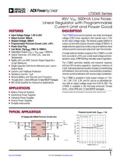
1 LTC415114151ffFor more information applicaTionFeaTuresapplicaTionsDescripTi onHigh Voltage I2C Current and Voltage Monitor The LT C 4151 is a high side power monitor that operates over a wide Voltage range of 7V to 80V. In default operation mode, the onboard 12-bit ADC continuously measures high side Current , input Voltage and an external Voltage . Data is reported through the I2C interface when polled by a host. The LTC4151 can also perform on-demand measurement in a snapshot mode. The LTC4151 features a dedicated shutdown pin to reduce power consumption. The LTC4151-1/LTC4151-2 feature split I2C data pins to drive opto-isolators. The data out on the LTC4151-1 is inverted while that on the LTC4151-2 is Side Power Sensing with Onboard ADC and I2Cn Wide Operating Voltage Range.
2 7V to 80Vn 12-Bit Resolution for Both Current and Voltagesn I2C Interfacen Additional ADC Input Monitors an External Voltagen Continuous Scan and Snapshot Modesn Shutdown Mode (LTC4151) Reduces Quiescent Current to 120 An Split SDA for Opto-Isolation (LTC4151-1/LTC4151-2)n Available in 10-Lead msop , 10-Lead 3mm 3mm DFN and 16-Lead SO Packagesn 48V Telecom Infrastructuren Automotiven Industrialn Consumer12-Bit ADC DNL and INL4151 CONTROLLERGNDLTC4151 SHDNVIN7V TO 80 VVOUTVINVDDMEASUREDVOLTAGESCLSDAADINADR1 SCL2k2kSDAADR0 GNDSENSE+SENSE CODE0 ADC DNL (LSB) TA01bCODE0 ADC INL (LSB) TA01cPARTPACKAGEFEATURED PINLTC4151DD10, MS10 SHDNLTC4151-1DD10, MS10 SDAOLTC4151-2S16 SDAOL, LT, LT C, LT M, Linear Technology and the Linear logo are registered trademarks and Hot Swap is a trademark of Linear Technology Corporation.
3 All other trademarks are the property of their respective more information MaxiMuM raTingsVIN Voltage .. to 90 VSENSE+, SENSE Voltages ..VIN 10V or to VIN + , ADR0 Voltages .. to 90 VADIN, SHDN, SDAO, SDAO Voltages .. to 6 VSCL, SDA, SDAI Voltages (Note 2) .. to , SDA, SDAI Clamp Current .. 5mA(Notes 1, 3)pin conFiguraTionOperating Temper atur e Range LTC4151C/ LTC4151C-1/LTC4151C-2 ..0 C to 70 C LTC4151I/ LTC4151I-1/LTC4151I-2 .. 40 C to 85 C LTC4151H .. 40 C to 125 CStorage Temper atur e Range msop , SO .. 65 C to 150 C DFN .. 65 C to 125 CLead Temper atur e (Soldering, 10 sec) msop , SO ..300 CLTC4151 LTC4151 TOP VIEWDD PACKAGE10-LEAD (3mm 3mm) PLASTIC DFN1096784511321 SENSE GNDSHDNSDASCLSENSE+VINADR1 ADR0 ADIN TJMAX = 150 C, JA = 45 C/W EXPOSED PAD (PIN 11) PCB GND CONNECTION OPTIONAL12345109876 TOP VIEWMS PACKAGE10-LEAD PLASTIC MSOPSENSE GNDSHDNSDASCLSENSE+VINADR1 ADR0 ADIN TJMAX = 150 C, JA = 85 C/WLTC4151-1 LTC4151-1 TOP VIEWDD PACKAGE10-LEAD (3mm 3mm) PLASTIC DFN10967845321 SENSE GNDSDAOSDAISCLSENSE+VINADR1 ADR0 ADIN11 TJMAX = 125 C, JA = 45 C/W EXPOSED PAD (PIN 11)
4 PCB GND CONNECTION OPTIONAL12345109876 TOP VIEWMS PACKAGE10-LEAD PLASTIC MSOPSENSE GNDSDAOSDAISCLSENSE+VINADR1 ADR0 ADIN TJMAX = 125 C, JA = 85 C/WLTC4151-2 TOP VIEWS PACKAGE16-LEAD PLASTIC SO12345678161514131211109 SENSE+VINNCNCADR1 NCADR0 NCSENSE NCNCGNDSDAOSDAISCLADIN TJMAX = 150 C, JA = 100 C/WLTC415134151ffFor more information inForMaTionLEAD FREE FINISHTAPE AND REELPART MARKING*PACKAGE DESCRIPTIONTEMPERATURE RANGELTC4151 CDD#PBFLTC4151 CDD#TRPBFLCWZ10-Lead (3mm 3mm) Plastic DFN0 C to 70 CLTC4151 IDD#PBFLTC4151 IDD#TRPBFLCWZ10-Lead (3mm 3mm) Plastic DFN 40 C to 85 CLTC4151 HDD#PBFLTC4151 HDD#TRPBFLCWZ10-Lead (3mm 3mm) Plastic DFN 40 C to 125 CLTC4151 CDD-1#PBFLTC4151 CDD-1#TRPBFLCXC10-Lead (3mm 3mm) Plastic DFN0 C to 70 CLTC4151 IDD-1#PBFLTC4151 IDD-1#TRPBFLCXC10-Lead (3mm 3mm)
5 Plastic DFN 40 C to 85 CLTC4151 CMS#PBFLTC4151 CMS#TRPBFLTCWY10-Lead Plastic MSOP0 C to 70 CLTC4151 IMS#PBFLTC4151 IMS#TRPBFLTCWY10-Lead Plastic msop 40 C to 85 CLTC4151 HMS#PBFLTC4151 HMS#TRPBFLTCWY10-Lead Plastic msop 40 C to 125 CLTC4151 CMS-1#PBFLTC4151 CMS-1#TRPBFLTCXB10-Lead Plastic MSOP0 C to 70 CLTC4151 IMS-1#PBFLTC4151 IMS-1#TRPBFLTCXB10-Lead Plastic msop 40 C to 85 CLTC4151CS-2#PBFLTC4151CS-2#TRPBFLTC4151 S-216-Lead Plastic SO0 C to 70 CLTC4151IS-2#PBFLTC4151IS-2#TRPBFLTC4151 S-216-Lead Plastic SO 40 C to 85 CConsult LT C Marketing for parts specified with wider operating temperature ranges. *The temperature grade is identified by a label on the shipping container. Consult LT C Marketing for information on non-standard lead based finish more information on lead free part marking, go to: For more information on tape and reel specifications, go to.
6 CharacTerisTicsSYMBOLPARAMETERCONDITIONS MINTYPMAXUNITSG eneral VINS upply Voltagel780 VIINS upply CurrentVIN = 48V, Normal Operation Mode VIN = 12V, Shutdown Model 300mA AISENSE+SENSE+ Input CurrentVIN, SENSE+, SENSE = 48Vl59 AISENSE SENSE Input CurrentVIN, SENSE+, SENSE = AVSHDN(TH) SHDN Input Input CurrentSHDN = 0Vl 3 5 8 AADCRESR esolution (No Missing Codes)(Note 4)l12 BitsVFSFull-Scale Voltage (SENSE+ SENSE ) VIN ADIN V VLSBLSB Step Size(SENSE+ SENSE ) VIN ADIN20 25 V mV mVTUET otal Unadjusted Error(SENSE+ SENSE ) VIN (Note 5) ADIN, C-Grade ADIN, I-, H-Gradel l l l 1 1% % % %VOSO ffset Error(SENSE+ SENSE ) VIN (Note 6) ADINl l l 5 6 8 LSB LSB LSB The l denotes the specifications which apply over the full operating temperature range, otherwise specifications are at TA = 25 C.
7 VIN is from 7V to 80V, unless noted. (Note 3)LTC415144151ffFor more information Nonlinearity(SENSE+ SENSE ) VIN (Note 5) ADINl l l 1 1 3 3 2 LSB LSB LSBsTTransition Noise(SENSE+ SENSE ) VIN 22 VRMS mVRMS VRMSfCONVC onversion Rate (Continuous Mode) Time (Snapshot Mode)(SENSE+ SENSE ) ADIN, VINl l53 2667 3385 42ms msRADINADIN Pin Input ResistanceADIN = 3Vl210 MWIADINADIN Pin Input CurrentADIN = 3Vl 2 AI2C InterfaceVADR(H)ADR0, ADR1 Input High (L)ADRO, ADRI Input Low (IN)ADRO, ADRI Input CurrentADR0, ADR1 = 0V or 3V ADR0, ADR1 = or l 8 70 A AVSDA(OL)SDA, SDAO, SDAO Output Low VoltageISDA, ISDAO, ISDAO = ,SCL(IN) SDA, SDAI, SDAO, SDAO, SCL Input CurrentSDA, SDAI, SDAO, SDAO, SCL = 5Vl0 2 AVSDA,SCL(TH) SDA, SDAI, SCL Input ,SCL(CL) SDA, SDAI, SCL Clamp VoltageISDA, ISDAI, ISCL = Interface Timing (Note 4)fSCL(MAX)Maximum SCL Clock Frequency400kHztLOWM inimum SCL Low Period stHIGHM inimum SCL High Period50600nstBUF(MIN)Minimum Bus Free Time Between Stop/Start stHD,STA(MIN)Minimum Hold Time After (Repeated) Start Condition140600nstSU,STA(MIN)Minimum Repeated Start Condition Set-Up Time30600nstSU,STO(MIN)Minimum Stop Condition Set-Up Time30600nstHD,DATI(MIN)Minimum Data Hold Time Input 1000nstHD,DATO(MIN)Minimum Data Hold Time Output300600900nstSU,DAT(MIN)
8 Minimum Data Set-Up Time Input30100nstSP(MAX) Maximum Suppressed Spike Pulse Width50110250nstRSTS tuck-Bus Reset TimeSCL or SDA/SDAI Held Low2033msCXSCL, SDA Input Capacitance510pFNote 1: Stresses beyond those listed under Absolute Maximum Ratings may cause permanent damage to the device. Exposure to any Absolute Maximum Rating condition for extended periods may affect device reliability and 2: Internal clamps limit the SCL, SDA (LTC4151) and SDAI (LTC4151-1/LTC4151-2) pins to a minimum of Driving these pins to voltages beyond the clamp may damage the part. The pins can be safely tied to higher voltages through a resistor that limits the Current below characTerisTics The l denotes the specifications which apply over the full operating temperature range, otherwise specifications are at TA = 25 C.
9 VIN is from 7V to 80V, unless noted. (Note 3)Note 3: All currents into pins are positive. All voltages are referenced to GND, unless otherwise 4: Guaranteed by design and not subject to 5: Integral nonlinearity and total unadjusted error of VIN are tested between 7V and 6: Offset error of VIN is defined by extrapolating the straight line measured between 7V and more information DNL (LSB) G04 CODE0 ADC INL (LSB) G05 Typical perForMance characTerisTicsSupply Current vs Supply Voltage (Normal Mode)Supply Current vs Supply Voltage (Shutdown Mode)ADC Total Unadjusted Error vs Code (ADIN Voltage ) ADC INL vs Code (ADIN Voltage )VIN = 12V, TA = 25 C, unless noted. ADC DNL vs Code (ADIN Voltage )SUPPLY Voltage (V)0 SUPPLY Current (mA) G01 40 C85 C25 CSUPPLY Voltage (V)0 SUPPLY Current ( A)2003008010002040604004151 G02 40 C85 C25 CCODE0 ADC TOTAL UNADJUSTED ERROR (%) G03 ADC Total Unadjusted Error vs Code (SENSE Voltage ) ADC DNL vs Code (SENSE Voltage ) ADC INL vs Code (SENSE Voltage )CODE0 ADC INL (LSB)014096 1 210242048307224151 G08 CODE0 ADC TOTAL UNADJUSTED ERROR (%) G06 CODE0 ADC DNL (LSB)014096 1 210242048307224151 G07 LTC415164151ffFor more information FuncTionsADIN: ADC Input.
10 The onboard ADC measures Voltage range between 0V and Tie to GND if , ADR0: I2C Device Address Inputs. Connecting ADR1 and ADR0 to VIN, GND or leaving the pins open configures one of nine possible addresses. See Table 1 in the Applications Information section for Pad (DD Package Only): Exposed pad may be left open or connected to device ground (GND).GND: Device Ground. SCL: I2C Bus Clock Input. Data is shifted in and out at the SDA pin on rising edges of SCL. This pin is driven by an open-collector output from a master controller. An external pull-up resistor or Current source is required and can be placed between SCL and VIN. The Voltage at SCL is internally clamped to 6V ( minimum).