Transcription of LF155/LF156/LF256/LF257/LF355/LF356/LF357 JFET …
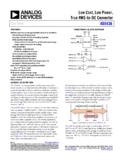
1 LF155/LF156/LF256/LF257/LF355/LF356/LF35 7 JFET input operational AmplifiersGeneral DescriptionThese are the first monolithic JFET input operational ampli-fiers to incorporate well matched, high voltage JFETs on thesame chip with standard bipolar transistors (BI-FET Tech-nology). These amplifiers feature low input bias and offsetcurrents/low offset voltage and offset voltage drift, coupledwith offset adjust which does not degrade drift orcommon-mode rejection. The devices are also designed forhigh slew rate, wide bandwidth, extremely fast settling time,low voltage and current noise and a low 1/f noise expensive hybrid and module FET op ampsnRugged JFETs allow blow-out free handling comparedwith MOSFET input devicesnExcellent for low noise applications using either high orlow source impedance very low 1/f cornernOffset adjust does not degrade drift or common-moderejection as in most monolithic amplifiersnNew output stage allows use of large capacitive loads(5,000 pF) without stability problemsnInternal compensation and large differential input voltagecapabilityApplicationsnPrecision high speed integratorsnFast D/A and A/D convertersnHigh impedance buffersnWideband, low noise, low drift amplifiersnLogarithmic amplifiersnPhotocell amplifiersnSample and Hold circuitsCommon FeaturesnLow input bias current:30pAnLow input Offset Current: 3pAnHigh input impedance: 1012 nLow input noise current.
2 NHigh common-mode rejection ratio: 100 dBnLarge dc voltage gain: 106 dBUncommon FeaturesLF155/LF355LF156/LF256/LF356LF25 7/LF357(AV=5)UnitsjExtremelyfast settlingtime sjFast slewrate51250V/ sjWide inputnoisevoltage201212 Simplified Schematic00564601*3pF in LF357 , BI-FET II are trademarks of National Semiconductor 2001LF155/LF156/LF256/LF257/LF355/LF356/ LF357 JFET input operational Amplifiers 2001 National Semiconductor Maximum Ratings(Note 1)If Military/Aerospace specified devices are required, contact the National Semiconductor Sales Office/Distributors foravailability and Voltage 22V 22V 18 VDifferential input Voltage 40V 40V 30 VInput Voltage Range (Note 2) 20V 20V 16 VOutput Short Circuit DurationContinuousContinuousContinuousTJ MAXH-Package150 C115 C115 CN-Package100 C100 CM-Package100 C100 CPower Dissipation at TA= 25 C (Notes1, 8)H-Package (Still Air)560 mW400 mW400 mWH-Package (400 LF/Min Air Flow)1200 mW1000 mW1000 mWN-Package670 mW670 mWM-Package380 mW380 mWThermal Resistance (Typical)
3 JAH-Package (Still Air)160 C/W160 C/W160 C/WH-Package (400 LF/Min Air Flow)65 C/W65 C/W65 C/WN-Package130 C/W130 C/WM-Package195 C/W195 C/W(Typical) JCH-Package23 C/W23 C/W23 C/WStorage Temperature Range 65 C to +150 C 65 C to +150 C 65 C to +150 CSoldering Information (Lead Temp.)Metal Can PackageSoldering (10 sec.)300 C300 C300 CDual-In-Line PackageSoldering (10 sec.)260 C260 C260 CSmall Outline PackageVapor Phase (60 sec.)215 C215 CInfrared (15 sec.)220 C220 CSee AN-450 Surface Mounting Methods and Their Effect on Product Reliability for other methods ofsoldering surface mount tolerance(100 pF discharged through )1000V1000V1000 VDC Electrical Characteristics(Note 3)SymbolParameterConditionsLF155/6LF256/ 7LF356 BLF355/6/7 UnitsMinTypMax MinTypMax MinTypMaxVOSI nput Offset VoltageRS=50 ,TA=25 C3535310mVOver VOS/ TAverage TC of InputOffset VoltageRS=50 555 V/ C TC/ VOSC hange in Average TCwith VOSA djustRS=50 , (Note 4) V/ Cper mVIOSI nput Offset CurrentTJ=25 C, (Notes 3, 5)320320350pATJ THIGH2012nALF155/LF156/LF256/LF257/LF355 /LF356 Electrical Characteristics(Continued)(Note 3)SymbolParameterConditionsLF155/6LF256/ 7LF356 BLF355/6/7 UnitsMinTypMax MinTypMax MinTypMaxIBInput Bias CurrentTJ=25 C, (Notes 3, 5)
4 301003010030200pATJ THIGH5058nARINI nput ResistanceTJ=25 C101210121012 AVOLL arge Signal VoltageGainVS= 15V, TA=25 C502005020025200V/mVVO= 10V, RL=2kOver Temperature252515V/mVVOO utput Voltage SwingVS= 15V, RL=10k 12 13 12 13 12 13 VVS= 15V, RL=2k 10 12 10 12 10 12 VVCMI nput Common-ModeVoltage RangeVS= 15V 11+ 11 +10+ 12 12 12 VCMRRC ommon-ModeRejection Ratio851008510080100dBPSRRS upply VoltageRejection Ratio(Note 6)851008510080100dBDC Electrical CharacteristicsTA=TJ= 25 C, VS= 15 VParameterLF155LF355LF156/256/257/356 BLF356LF357 UnitsTypMaxTypMaxTypMaxTypMaxTypMaxSuppl yCurrent2424 5 7 510510mAAC Electrical CharacteristicsTA=TJ= 25 C, VS= 15 VSymbolParameterConditionsLF155/355LF156 /256/356 BLF156/256/356/LF356 BLF257/357 UnitsTypMinTypTypSRSlew RateLF155/6:AV=1, sLF357: AV=550V/ sGBWGain Bandwidth Time to (Note 7) senEquivalent input NoiseVoltageRS=100 f=100 Hz251515f=1000 Hz201212inEquivalent input CurrentNoisef=100 Capacitance333pFNotes for Electrical CharacteristicsNote 1:The maximum power dissipation for these devices must be derated at elevated temperatures and is dictated by TJMAX, JA, and the ambient temperature,TA.
5 The maximum available power dissipation at any temperature is PD=(TJMAX TA)/ JAor the 25 C PdMAX, whichever is 2:Unless otherwise specified the absolute maximum negative input voltage is equal to the negative power supply 3:Unless otherwise stated, these test conditions apply:LF155/LF156/LF256/LF257/LF355/LF35 6 for Electrical Characteristics(Continued)LF155/156LF256 /257LF356 BLF355/6/7 Supply Voltage, VS 15V VS 20V 15V VS 20V 15V VS 20 VVS= 15 VTA 55 C TA +125 C 25 C TA +85 C0 C TA +70 C0 C TA +70 CTHIGH+125 C+85 C+70 C+70 Cand VOS,IBand IOSare measured at VCM= 4:The Temperature Coefficient of the adjusted input offset voltage changes only a small amount ( V/ C typically) for each mV of adjustment from its originalunadjusted value. Common-mode rejection and open loop voltage gain are also unaffected by offset 5:The input bias currents are junction leakage currents which approximately double for every 10 C increase in the junction temperature, TJ.
6 Due to limitedproduction test time, the input bias currents measured are correlated to junction temperature. In normal operation the junction temperature rises above the ambienttemperature as a result of internal power dissipation, Pd. TJ=TA+ JAPd where JAis the thermal resistance from junction to ambient. Use of a heat sink isrecommended if input bias current is to be kept to a 6:Supply Voltage Rejection is measured for both supply magnitudes increasing or decreasing simultaneously, in accordance with common 7:Settling time is defined here, for a unity gain inverter connection using 2 k resistors for the LF155/6. It is the time required for the error voltage (the voltageat the inverting input pin on the amplifier) to settle to within of its final value from the time a 10V step input is applied to the inverter. For the LF357, AV= 5,the feedback resistor from output to input is 2k and the output step is 10V (See Settling Time Test Circuit).Note 8:Max. Power Dissipation is defined by the package characteristics.
7 Operating the part near the Max. Power Dissipation may cause the part to operate outsideguaranteed DC Performance CharacteristicsCurves are for LF155 and LF156 unless Bias CurrentInput Bias Current0056463700564638 input Bias CurrentVoltage Swing0056463900564640LF155/LF156/LF256/L F257/LF355/LF356 DC Performance CharacteristicsCurves are for LF155 and LF156 unless otherwisespecified. (Continued)Supply CurrentSupply Current0056464100564642 Negative Current LimitPositive Current Limit0056464300564644 Positive Common-ModeInput Voltage LimitNegative Common-ModeInput Voltage Limit0056464500564646LF155/LF156/LF256/L F257/LF355/LF356 DC Performance CharacteristicsCurves are for LF155 and LF156 unless otherwisespecified. (Continued)Open Loop Voltage GainOutput Voltage Swing0056464700564648 Typical AC Performance CharacteristicsGain BandwidthGain Bandwidth0056464900564650 Normalized Slew RateOutput Impedance0056465100564652LF155/LF156/LF2 56/LF257/LF355/LF356 AC Performance Characteristics(Continued)Output ImpedanceLF155 Small Signal Pulse Response, AV=+10056465300564605LF156 Small Signal Pulse Response, AV= +1LF155 Large Signal Pulse Response, AV=+10056460600564608LF156 Large Signal PulsResponse, AV= +1 Inverter Settling Time0056460900564655LF155/LF156/LF256/LF 257/LF355/LF356 AC Performance Characteristics(Continued)Inverter Settling TimeOpen Loop Frequency Response0056465600564657 Bode PlotBode Plot0056465800564659 Bode PlotCommon-Mode Rejection Ratio0056466000564661LF155/LF156/LF256/L F257/LF355/LF356 AC Performance Characteristics(Continued)
8 Power Supply Rejection RatioPower Supply Rejection Ratio0056466200564663 Undistorted Output Voltage SwingEquivalent input Noise Voltage0056466400564665 Equivalent input NoiseVoltage (Expanded Scale)00564666LF155/LF156/LF256/LF257/LF 355/LF356 Schematic00564613*C = 3pF in LF357 Diagrams(Top Views)Metal Can Package (H)00564614 Order Number LF155H, LF156H, LF256H, LF257H,LF356BH, LF356H, or LF357 HSee NS Package Number H08C*Available per JM38510/11401 or JM38510/11402 Dual-In-Line Package (M and N)00564629 Order Number LF356M, LF356MX, LF355N, or LF356 NSee NS Package Number M08A or N08 EApplication HintsThese are op amps with JFET input devices. These JFET shave large reverse breakdown voltages from gate to sourceand drain eliminating the need for clamps across the large differential input voltages can easily be ac-commodated without a large increase in input current. Themaximum differential input voltage is independent of thesupply voltages. However, neither of the input voltagesshould be allowed to exceed the negative supply as this willcause large currents to flow which can result in a the negative common-mode limit on either inputwill force the output to a high state, potentially causing aLF155/LF156/LF256/LF257/LF355/LF356 Hints(Continued)reversal of phase to the output.
9 Exceeding the negativecommon-mode limit on both inputs will force the amplifieroutput to a high state. In neither case does a latch occursince raising the input back within the common-mode rangeagain puts the input stage and thus the amplifier in a normaloperating the positive common-mode limit on a single inputwill not change the phase of the output however, if bothinputs exceed the limit, the output of the amplifier will beforced to a high amplifiers will operate with the common-mode inputvoltage equal to the positive supply. In fact, thecommon-mode voltage can exceed the positive supply byapproximately 100 mV independent of supply voltage andover the full operating temperature range. The positive sup-ply can therefore be used as a reference on an input as, forexample, in a supply current monitor and/or should be taken to ensure that the power supplyfor the integrated circuit never becomes reversed in polarityor that the unit is not inadvertently installed backwards in asocket as an unlimited current surge through the resultingforward diode within the IC could cause fusing of the internalconductors and result in a destroyed of the bias currents in these amplifiers are set by FETcurrent sources.
10 The drain currents for the amplifiers aretherefore essentially independent of supply with most amplifiers, care should be taken with leaddress, component placement and supply decoupling in orderto ensure stability. For example, resistors from the output toan input should be placed with the body close to the input tominimize pickup and maximize the frequency of the feed-back pole by minimizing the capacitance from the input feedback pole is created when the feedback around anyamplifier is resistive. The parallel resistance and capacitancefrom the input of the device (usually the inverting input ) to ACground set the frequency of the pole. In many instances thefrequency of this pole is much greater than the expected 3dBfrequency of the closed loop gain and consequently there isnegligible effect on stability margin. However, if the feedbackpole is less than approximately six times the expected 3 dBfrequency a lead capacitor should be placed from the outputto the input of the op amp.