Transcription of 3 nV/√Hz, Low Power Instrumentation Amplifier …
1 3 nV/ Hz, Low Power Instrumentation AmplifierEnhanced product ad8421 -EP Rev. 0 Document Feedback Information furnished by analog devices is believed to be accurate and reliable. However, no responsibility is assumed by analog devices for its use, nor for any infringements of patents or other rights of third parties that may result from its use. Specifications subject to change without notice. No license is granted by implication or otherwise under any patent or patent rights of analog devices . Trademarks and registered trademarks are the property of their respective owners. One Technology Way, Box 9106, Norwood, MA 02062-9106, : 2013 analog devices , Inc. All rights reserved. Technical Support FEATURES Specified from 55 C to 125 C V/ C maximum input offset voltage drift 5 ppm/ C maximum gain drift (G = 1) Low Power mA maximum supply current Low noise nV/ Hz maximum input voltage noise at 1 kHz 200 fA/ Hz current noise at 1 kHz Excellent ac specifications 2 MHz bandwidth (G = 100) s settling time to (G = 10) 80 dB minimum CMRR at 20 kHz (G = 1) High precision dc performance 84 dB CMRR minimum (G = 1) 2 nA maximum input bias current Inputs protected to 40 V from opposite supply Gain set with a single resistor (G = 1 to 10,000) enhanced product FEATURES Supports defense and aerospace applications (AQEC standard) Military temperature range ( 55 C to +125 C)
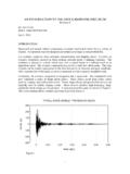
2 Controlled manufacturing baseline One assembly/test site One fabrication site enhanced product change notification Qualification data available on request PIN CONNECTION DIAGRAM TOP VIEW(Not to Scale) IN1RG2RG3+IN4+VS8 VOUT7 REF6 VS5AD8421-EP11139-001 Figure 1. 10 1n1001 MTOTAL NOISE DENSITY AT 1kHz (V/ Hz)SOURCE RESISTANCE, RS ( )1 100n10n1k10k100kG = 100AD8421 BEST AVAILABLE1mA LOW Power IN-AMPBEST AVAILABLE7mA LOW NOISE IN-AMPRS NOISE ONLY11139-078 Figure 2. Noise Density vs. Source Resistance GENERAL DESCRIPTION The ad8421 -EP is a low cost, low Power , extremely low noise, ultralow bias current, high speed Instrumentation Amplifier that is ideally suited for a broad spectrum of signal conditioning and data acquisition applications. This product features extremely high CMRR, allowing it to extract low level signals in the presence of high frequency common-mode noise over a wide temperature range.
3 The 10 MHz bandwidth, 35 V/ s slew rate, and s settling time to (G = 10) allow the ad8421 -EP to amplify high speed signals and excel in applications that require high channel count, multiplexed systems. Even at higher gains, the current feedback architecture maintains high performance; for example, at G = 100, the bandwidth is 2 MHz and the settling time is s. The ad8421 -EP has excellent distortion performance, making it suitable for use in demanding applications such as vibration analysis. The ad8421 -EP delivers 3 nV/ Hz input voltage noise and 200 fA/ Hz current noise with only 2 mA quiescent current, making it an ideal choice for measuring low level signals. For applications with high source impedance, the ad8421 -EP employs innovative process technology and design techniques to provide noise performance that is limited only by the sensor.
4 The ad8421 -EP uses unique protection methods to ensure robust inputs while still maintaining very low noise. This protection allows input voltages up to 40 V from the opposite supply rail without damage to the part. A single resistor sets the gain from 1 to 10,000. The reference pin can be used to apply a precise offset to the output voltage. The ad8421 -EP is specified over the military temperature range of 55 C to +125 C. It is available in an 8-lead MSOP package. Additional application and technical information can be found in the ad8421 data sheet. ad8421 -EP enhanced product Rev. 0 | Page 2 of 20 TABLE OF CONTENTS Features .. 1 General Description .. 1 Revision History .. 2 Specifications .. 3 Absolute Maximum Ratings .. 6 Thermal Resistance .. 6 ESD Pin Configuration and Function Descriptions.
5 7 Typical Performance Characteristics ..8 Outline Dimensions .. 18 Ordering Guide .. 18 REVISION HISTORY 5/13 Revision 0: Initial Ve r s i o n enhanced product ad8421 -EP Rev. 0 | Page 3 of 20 SPECIFICATIONS VS = 15 V, VREF = 0 V, TA = 25 C, G = 1, RL = 2 k , unless otherwise noted. Table 1. Parameter Te s t Conditions/ Comments Min Typ Max Unit COMMON-MODE REJECTION RATIO (CMRR) CMRR DC to 60 Hz with 1 k Source Imbalance VCM = 10 V to +10 V G = 1 84 dB G = 10 104 dB G = 100 124 dB G = 1000 134 dB Over Temperature, G = 1 TA = 55 C to +125 C 80 dB CMRR at 20 kHz VCM = 10 V to +10 V G = 1 80 dB G = 10 90 dB G = 100 100 dB G = 1000 100 dB NOISE Voltage Noise, 1 kHz1 VIN+, VIN = 0 V Input Voltage Noise, eni 3 nV/ Hz Output Voltage Noise, eno 60 nV/ Hz Peak to Peak, RTI f = Hz to 10 Hz G = 1 2 V p-p G = 10 V p-p G = 100 to 1000 V p-p Current Noise Spectral Density f = 1 kHz 200 fA/ Hz Peak to Peak, RTI f = Hz to 10 Hz 18 pA p-p VOLTAGE OFFSET2 Input Offset Voltage.
6 VOSI VS = 5 V to 15 V 70 V Over Temperature TA = 55 C to +125 C 160 V Average TC V/ C Output Offset Voltage, VOSO 600 V Over Temperature TA = 55 C to +125 C mV Average TC 9 V/ C Offset RTI vs. Supply (PSR) VS = V to 18 V G = 1 90 120 dB G = 10 110 120 dB G = 100 124 130 dB G = 1000 130 140 dB INPUT CURRENT Input Bias Current 1 2 nA Over Temperature TA = 55 C to +125 C 8 nA Average TC 50 pA/ C Input Offset Current 2 nA Over Temperature TA = 55 C to +125 C 3 nA Average TC 1 pA/ C ad8421 -EP enhanced product Rev. 0 | Page 4 of 20 Parameter Te s t Conditions/ Comments Min Typ Max Unit DYNAMIC RESPONSE Small Signal Bandwidth 3 dB G = 1 10 MHz G = 10 10 MHz G = 100 2 MHz G = 1000 MHz Settling Time 10 V step G = 1 s G = 10 s G = 100 s G = 1000 5 s Settling Time 10 V step G = 1 1 s G = 10 s G = 100 s G = 1000 6 s Slew Rate G = 1 to 100 35 V/ s GAIN3 G = 1 + ( k /RG) Gain Range 1 10,000 V/V Gain Error VOUT = 10 V G = 1 % G = 10 to 1000 % Gain Nonlinearity VOUT = 10 V to +10 V G = 1 RL 2 k 1 ppm RL = 600 1 3 ppm G = 10 to 1000 RL 600 30 50 ppm VOUT = 5 V to +5 V 5 10 ppm Gain vs.
7 Temperature3 G = 1 5 ppm/ C G > 1 80 ppm/ C INPUT Input Impedance Differential 30||3 G ||pF Common Mode 30||3 G ||pF Input Operating Voltage Range4 VS = V to 18 V VS + +VS V Over Temperature TA = 55 C VS + +VS V TA = +125 C VS + +VS V OUTPUT RL = 2 k Output Swing VS = V to 18 V VS + +VS V Over Temperature TA = 55 C to +125 C VS + +VS V Short-Circuit Current 65 mA REFERENCE INPUT RIN 20 k IIN VIN+, VIN = 0 V 20 24 A Voltage Range VS +VS V Reference Gain to Output 1 V/V enhanced product ad8421 -EP Rev. 0 | Page 5 of 20 Parameter Te s t Conditions/ Comments Min Typ Max Unit Power SUPPLY Operating Range Dual supply 18 V Single supply 5 36 V Quiescent Current 2 mA Over Temperature TA = 55 C to +125 C mA TEMPERATURE RANGE For Specified Performance 55 +125 C 1 Total voltage noise = (eni2 + (eno/G)2 + eRG2).
8 See the ad8421 data sheet for more information. 2 Total RTI VOS = (VOSI) + (VOSO/G). 3 These specifications do not include the tolerance of the external gain setting resistor, RG. For G > 1, add RG errors to the specifications given in this table. 4 Input voltage range of the ad8421 -EP input stage only. The input range can depend on the common-mode voltage, differential voltage, gain, and reference voltage. See the Typical Performance Characteristics section for more information. ad8421 -EP enhanced product Rev. 0 | Page 6 of 20 ABSOLUTE MAXIMUM RATINGS Table 2. Parameter Rating Supply Voltage 18 V Output Short-Circuit Current Duration Indefinite Maximum Voltage at IN or +IN1 VS + 40 V Minimum Voltage at IN or +IN +VS 40 V Maximum Voltage at REF2 +VS + V Minimum Voltage at REF VS V Storage Temperature Range 65 C to +150 C Operating Temperature Range 55 C to +125 C Maximum Junction Temperature 150 C ESD Human Body Model 2 kV Charged Device Model kV Machine Model kV 1 For voltages beyond these limits, use input protection resistors.
9 See the ad8421 data sheet for more information. 2 There are ESD protection diodes from the reference input to each supply, so REF cannot be driven beyond the supplies in the same way that +IN and IN can. See the ad8421 data sheet for more information. Stresses above those listed under Absolute Maximum Ratings may cause permanent damage to the device. This is a stress rating only; functional operation of the device at these or any other conditions above those indicated in the operational section of this specification is not implied. Exposure to absolute maximum rating conditions for extended periods may affect device reliability. THERMAL RESISTANCE JA is specified for a device in free air using a 4-layer JEDEC printed circuit board (PCB). Table 3. Package JA Unit 8-Lead MSOP C/W ESD CAUTION enhanced product ad8421 -EP Rev.
10 0 | Page 7 of 20 PIN CONFIGURATION AND FUNCTION DESCRIPTIONS TOP VIEW(Not to Scale) IN1RG2RG3+IN4+VS8 VOUT7 REF6 VS5AD8421-EP11139-002 Figure 3. Pin Configuration Table 4. Pin Function Descriptions Pin No. Mnemonic Description 1 IN Negative Input Terminal. 2, 3 RG Gain Setting Terminals. Place resistor across the RG pins to set the gain. G = 1 + ( k /RG). 4 +IN Positive Input Terminal. 5 VS Negative Power Supply Terminal. 6 REF Reference Voltage Terminal. Drive this terminal with a low impedance voltage source to level shift the output.