Transcription of 20 V, 200 mA, Low Noise, CMOS LDO Linear …
1 20 v , 200 ma , Low Noise, cmos LDO Linear RegulatorData Sheet ADP7118 Rev. E Document Feedback Information furnished by analog devices is believed to be accurate and reliable. However, no responsibility is assumed by analog devices for its use, nor for any infringements of patents or other rights of third parties that may result from its use. Specifications subject to change without notice. No license is granted by implication or otherwise under any patent or patent rights of analog devices . Trademarks and registered trademarks are the property of their respective owners. One Technology Way, Box 9106, Norwood, MA 02062-9106, : 2014 2019 analog devices , Inc. All rights reserved. Technical Support FEATURES low noise : 11 V rms independent of fixed output voltage PSRR of 88 dB at 10 kHz, 68 dB at 100 kHz, 50 dB at 1 MHz, VOUT 5 V, VIN = 7 V Input voltage range: V to 20 v Maximum output current: 200 ma Initial accuracy: Accuracy over line, load, and temperature to + , TJ = 40 C to +85 C , TJ = 40 C to +125 C Low dropout voltage: 200 mV (typical) at a 200 ma load, VOUT = 5 V User programmable soft start (LFCSP and SOIC only) Low quiescent current, IGND = 50 A (typical) with no load Low shutdown current: A at VIN = 5 V, A at VIN = 20 v Stable with a small F ceramic output capacitor Fixed output voltage options.
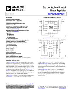
2 V, V, V, V, and V 16 standard voltages between V and V are available Adjustable output from V to VIN VDO, output can be adjusted above initial set point Precision enable 2 mm 2 mm, 6-lead LFCSP, 8-Lead SOIC, 5-Lead TSOT AEC-Q100 qualified for automotive applications APPLICATIONS Regulation to noise sensitive applications ADC and DAC circuits, precision amplifiers, power for VCO VTUNE control Communications and infrastructure Medical and healthcare Industrial and instrumentation Supported by ADIsimPower tool TYPICAL APPLICATION CIRCUITS GNDENSSVINVOUTADP7118 ONOFFVIN = 6 VVOUT = 5 FCSS1nF11849-001 Figure 1. ADP7118 with Fixed Output Voltage, 5 V GNDENSSVINVOUTADP7118 ONOFFVIN = 7 VVOUT = 6 FCSS1nF2k 10k 11849-002 Figure 2. ADP7118 with 5 V Output Adjusted to 6 V GENERAL DESCRIPTION The ADP7118 is a cmos , low dropout (LDO) Linear regulator that operates from V to 20 v and provides up to 200 ma of output current. This high input voltage LDO is ideal for the regulation of high performance analog and mixed-signal circuits operating from 20 v down to V rails.
3 Using an advanced proprietary architecture, the device provides high power supply rejection, low noise , and achieves excellent line and load transient response with a small F ceramic output capacitor. The ADP7118 regulator output noise is 11 V rms independent of the output voltage for the fixed options of 5 V or less. The ADP7118 is available in 16 fixed output voltage options. The following voltages are available from stock: V (adjustable), V, V, V, V, and V. Additional voltages available by special order are V, V, V, V, V, V, V, V, V, and V. Each fixed output voltage can be adjusted above the initial set point with an external feedback divider. This allows the ADP7118 to provide an output voltage from V to VIN VDO with high PSRR and low noise . User programmable soft start with an external capacitor is available in the LFCSP and SOIC packages. The ADP7118 is available in a 6-lead, 2 mm 2 mm LFCSP making it not only a very compact solution, but it also provides excellent thermal performance for applications requiring up to 200 ma of output current in a small, low profile footprint.
4 The ADP7118 is also available in a 5-lead TSOT and an 8-lead SOIC. ADP7118 Data Sheet Rev. E | Page 2 of 24 TABLE OF CONTENTS Features .. 1 Applications .. 1 Typical Application Circuits .. 1 General Description .. 1 Revision History .. 2 Specifications .. 3 Input and Output Capacitance, Recommended Specifications .. 4 Absolute Maximum Ratings .. 5 Thermal Data .. 5 Thermal Resistance .. 5 ESD Caution .. 5 Pin Configurations and Function Descriptions .. 6 Typical Performance Characteristics .. 7 Theory of Operation .. 13 Applications Information .. 14 ADIsimPower Design Tool .. 14 Capacitor Selection .. 14 Programable Precision Enable .. 15 Soft Start .. 15 noise Reduction of the ADP7118 in Adjustable Mode .. 16 Effect of noise Reduction on Start-Up Time .. 16 Current-Limit and Thermal Overload Protection .. 17 Thermal Considerations .. 17 Printed Circuit Board Layout Considerations .. 20 Outline Dimensions .. 22 Ordering Guide .. 23 Automotive Products.
5 24 REVISION HISTORY 9/2019 Rev. D to Rev. E Changes to Features 1 Change to Package Column, Table 9 .. 21 Changes to Ordering Guide .. 23 Added Automotive Products Section .. 24 4/2018 Rev. C to Rev. D Changes to Features 1 Updated Outline Dimensions .. 22 Changes to Ordering Guide .. 23 11/2016 Rev. B to Rev. C Changes to Features Section and General Description Section .. 1 Changes to Ordering Guide .. 23 7/2016 Rev. A to Rev. B Change to Table 5 .. 6 Change to Figure 42 .. 13 Changes to Programmable Precision Enable Section and Soft Start Section .. 15 Added Effect of noise Reduction on Start-Up Time Section .. 16 12/2014 Rev. 0 to Rev. A Changes to Figure 36 to Figure 41 .. 12 Changes to Figure 44 .. 14 9/2014 Revision 0: Initial Version Data Sheet ADP7118 Rev. E | Page 3 of 24 SPECIFICATIONS VIN = VOUT + 1 V or V, whichever is greater, VOUT = 5 V, EN = VIN, IOUT = 10 mA, CIN = COUT = F, CSS = 0 pF, TA = 25 C for typical specifications, TJ = 40 C to +125 C for minimum/maximum specifications, unless otherwise noted.
6 Table 1. Parameter Symbol Test Conditions/Comments Min Typ Max Unit INPUT VOLTAGE RANGE VIN 20 v OPERATING SUPPLY CURRENT IGND IOUT = 0 A 50 140 A IOUT = 10 mA 80 190 A IOUT = 200 ma 180 320 A SHUTDOWN CURRENT IGND-SD EN = GND A EN = GND, VIN = 20 v A EN = GND 10 A OUTPUT VOLTAGE ACCURACY Output Voltage Accuracy VOUT IOUT = 10 mA, TJ = 25 C + % 100 A < IOUT < 200 ma , VIN = (VOUT + 1 V) to 20 v , TJ = 40 C to +85 C + % 100 A < IOUT < 200 ma , VIN = (VOUT + 1 V) to 20 v + % LINE REGULATION VOUT/ VIN VIN = (VOUT + 1 V) to 20 v + %/V LOAD REGULATION1 VOUT/ IOUT IOUT = 100 A to 200 ma %/mA SENSE INPUT BIAS CURRENT SENSEI-BIAS 100 A < IOUT < 200 ma VIN = (VOUT + 1 V) to 20 v 10 1000 nA DROPOUT VOLTAGE2 VDROPOUT IOUT = 10 mA 30 60 mV IOUT = 200 ma 200 420 mV START-UP TIME3 tSTART-UP VOUT = 5 V 380 s SOFT START SOURCE CURRENT SSI-SOURCE SS = GND A CURRENT-LIMIT THRESHOLD4 ILIMIT 250 360 460 mA THERMAL SHUTDOWN Thermal Shutdown Threshold TSSD TJ rising 150 C Thermal Shutdown Hysteresis TSSD-HYS 15 C UNDERVOLTAGE THRESHOLDS Input Voltage Rising UVLORISE V Input Voltage Falling UVLOFA L L V Hysteresis UVLOHYS 230 mV PRECISION EN INPUT V VIN 20 v Logic High ENHIGH
7 V Logic Low ENLOW V Logic Hysteresis ENHYS 100 mV Leakage Current IEN-LKG EN = VIN or GND 1 A Delay Time tEN-DLY From EN rising from 0 V to VIN to VOUT 80 s OUTPUT noise OUTNOISE 10 Hz to 100 kHz, all output voltage options 11 V rms POWER SUPPLY REJECTION RATIO PSRR 1 MHz, VIN = 7 V, VOUT = 5 V 50 dB 100 kHz, VIN = 7 V, VOUT = 5 V 68 dB 10 kHz, VIN = 7 V, VOUT = 5 V 88 dB 1 Based on an endpoint calculation using 100 A and 200 ma loads.
8 See Figure 7 for typical load regulation performance for loads less than 1 mA. 2 Dropout voltage is defined as the input-to-output voltage differential when the input voltage is set to the nominal output voltage. Dropout applies only for output voltages above V. 3 Start-up time is defined as the time between the rising edge of EN to OUT being at 90% of the nominal value. 4 Current-limit threshold is defined as the current at which the output voltage drops to 90% of the specified typical value. For example, the current limit for a V output voltage is defined as the current that causes the output voltage to drop to 90% of V or V. ADP7118 Data Sheet Rev. E | Page 4 of 24 INPUT AND OUTPUT CAPACITANCE, RECOMMENDED SPECIFICATIONS Table 2. Parameter Symbol Test Conditions/Comments Min Typ Max Unit INPUT AND OUTPUT CAPACITANCE Minimum Capacitance1 CMIN TA = 40 C to +125 C F Capacitor Effective Series Resistance (ESR) RESR TA = 40 C to +125 C 1 The minimum input and output capacitance must be greater than F over the full range of operating conditions.
9 The full range of operating conditions in the application must be considered during device selection to ensure that the minimum capacitance specification is met. X7R and X5R type capacitors are recommended, while Y5V and Z5U capacitors are not recommended for use with any LDO. Data Sheet ADP7118 Rev. E | Page 5 of 24 ABSOLUTE MAXIMUM RATINGS Table 3. Parameter Rating VIN to GND V to +24 V VOUT to GND V to VIN EN to GND V to +24 V SENSE/ADJ to GND V to +6 V SS to GND V to VIN or +6 V (whichever is less) Storage Temperature Range 65 C to +150 C Junction Temperature (TJ) 150 C Operating Ambient Temperature ( TA) Range 40 C to +125 C Soldering Conditions JEDEC J-STD-020 Stresses at or above those listed under Absolute Maximum Ratings may cause permanent damage to the product. This is a stress rating only; functional operation of the product at these or any other conditions above those indicated in the operational section of this specification is not implied.
10 Operation beyond the maximum operating conditions for extended periods may affect product reliability. THERMAL DATA Absolute maximum ratings apply individually only, not in combination. The ADP7118 can be damaged when the junction temperature limits are exceeded. Monitoring ambient temperature does not guarantee that TJ is within the specified temperature limits. In applications with high power dissipation and poor thermal resistance, the maximum ambient temperature may have to be derated. In applications with moderate power dissipation and low printed circuit board (PCB) thermal resistance, the maximum ambient temperature can exceed the maximum limit as long as the junction temperature is within specification limits. The junction temperature of the device is dependent on the ambient temperature, the power dissipation (PD) of the device, and the junction-to-ambient thermal resistance of the package ( JA). Maximum TJ is calculated from the TA and PD using the formula TJ = TA + (PD JA) (1) JA of the package is based on modeling and calculation using a 4-layer board.