Transcription of AXE101 PICAXE-08M2 Cyberpet Kit
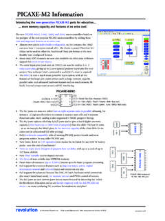
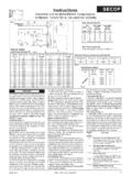
1 AXE101 Cyberpet Kit Revolution Education Ltd 2002-2016 May be copied for educational use. 1 AXE101 PICAXE-08M2 Cyberpet Kit The Cyberpet project uses a PICAXE-08M2 microcontroller with two LEDs as the pets eyes and a piezo sounder as a voice for the pet. The project also uses a switch so that the pet can respond to touch , and a Light Dependent Resistor (LDR) so that the pet can tell whether it is light or dark. output LED eye input LDR output piezo sounder input push switch output LED eye Remember not to confuse the chip leg number with the input/output pin number! For the full datasheet please see AXE101 Cyberpet Kit Revolution Education Ltd 2002-2016 May be copied for educational use.
2 2 Kit Contents 3 R1,R2,R6 RES-10K 10k resistor (brown black orange gold) 1 R3 RES-22K 22k resistor (red red orange gold) 2 R4,R5 RES-330 330R resistor (orange orange brown gold) 1 LK1 wire link (use offcut resistor leg) 2 LED1,LED2 LED001 5mm red LED 1 PZ SPE003* uncased piezo sounder 1 LDR SEN002 miniature light dependent resistor 1 SW1 SEN030 miniature 6mm switch 1 IC1 ICH008 8 pin IC socket 1 IC1 AXE007M2 PICAXE-08M2 microcontroller 1 CT1 CON039 PICAXE download socket 1 BT1 BAT016 battery clip 1 BT1 BAT013 (3xAA) battery box 1 PCB Cyberpet printed circuit board * The cased piezo SPE001 may be purchased separately if preferred to uncased SPE003. Loose wire (not supplied, if connecting LEDs and LDR by wires) Tools required: soldering iron and solder, side cutters For the full please datasheet see AXE101 Cyberpet Kit Revolution Education Ltd 2002-2016 May be copied for educational use.
3 3 What is a microcontroller? A microcontroller is often described as a 'computer-on-a-chip'. It can be used as an electronic brain to control a product, toy or machine. The microcontroller is an integrated circuit ("chip") that contains memory (to store the program), a processor (to process and carry out the program) and input/ output pins (to connect switches, sensors and output devices like motors). Microcontrollers are purchased 'blank' and then programmed with a specific control program. This program is written on a computer and then 'downloaded' into the microcontroller chip. Once programmed the microcontroller is built into a product to make the product more intelligent and easier to use. Example use of a microcontroller. In most toy shops there are now lots of intelligent 'toys' available.
4 These toys can move, make noises and respond to being touched or being placed in a dark place. An example of one such toy is the 'Furby' made by Tiger Electronics. The Furby has a microcontroller as its electronic 'brain' and reacts (to being touched or being placed in the dark) by moving or making sounds. The Furby reacts to the outside world by sensors and switches. It has a push switch on its front and back, a microswitch in its mouth and a light sensor (LDR) between its eyes. There is also a microphone on its side so that it can detect sounds. The Furby's movement is provided by an electric motor. It also has a speaker to generate sounds and an infra-red LED so that it can send signals to other Furby's that might be nearby. AXE101 Cyberpet Kit Revolution Education Ltd 2002-2016 May be copied for educational use.
5 4 Therefore the microcontroller is the 'brain' of the Furby. Microcontrollers are powerful electronic components that have a memory and can be programmed to switch things on and off in a special sequence. The microcontroller in the Furby, for instance, has been programmed to switch off the motor and speaker when the light sensor has detected it to be dark ( the Furby goes to sleep). AXE101 Cyberpet Kit Revolution Education Ltd 2002-2016 May be copied for educational use. 5 Cyberpet Design Brief Design and make an electronic Cyberpet toy. The Cyberpet must be programmed with its own personality so that it reacts in a unique way. Design Specification Points 1) The design will use a PICAXE-08M2 microcontroller as its brain. 2) The design will include LED eyes, a piezo sounder to generate noises and could also optionally use a motor to generate movement.
6 3) The design will be able to react to touch and changes in light level. 4) The Cyberpet can be designed as a flat 2-dimensional panel or as a full 3- dimensional creature. Block Diagram The block diagram for your Cyberpet may look like this: Designing Your Own Cyberpet Your Cyberpet can be any shape or size you choose. You may like to design the face of the pet using a computer graphics program or by drawing by hand. You could scan in a picture of a living animal, or design a completely new robot animal. Things to think about: The electronic components will need to be mounted inside (or underneath) your Cyberpet . The LEDs and LDR will need to poke through holes (normally 5mm wide, although LEDs are also available in other sizes). You should also think carefully about where the batteries are going to be stored and where the wires are going to be connected.
7 AXE101 Cyberpet Kit Revolution Education Ltd 2002-2016 May be copied for educational use. 6 Assembly How you build your Cyberpet PCB will depend on the shape and size of your design. You may solder all the components directly onto the board, or you may connect some of the components ( the LEDs, the LDR and the switch) by longer pieces of wire so they can be fitted inside your Cyberpet . These instructions presume you are soldering all the components directly on the board. The instructions are identical if you are using longer wires to join some components, although you must be even more careful you get the wires around the correct way on the LEDs 1) Place the three 10k (brown black orange gold) resistors in position. Bend the legs to hold the resistors in position and then solder.
8 2) Place the 22k (red red orange gold) and two 330 (orange orange brown gold) resistors in position. Bend the legs to hold the resistors in position and then solder. 3) Using an off cut resistor leg, make a wire loop over the letters PX marked beside the 330R resistors. Solder in position. (Ignore the hole above the holes marked CF). 4) Push the PICAXE stereo download socket onto the PCB and make sure it clicks into position (so that it lies flat on the board). Solder the five metal square contacts (the five round plastic support post holes do not have to be soldered). Do not worry if the solder joins on the two metal contacts either side of the socket as they are supposed to be joined anyway. 5) Push the IC socket into position. Make sure the notch at one end points up towards the stereo download socket.
9 Fold the legs over to hold the socket in position and then solder. 6) Solder the LDR and two LEDs into position. Make sure the flat on one side of the LED aligns with the flat marked on the PCB. 7) Solder the switch in position (note that it only fits one way around). If using wires solder one wire into either one of the two bottom holes and the other wire into either one of the two top holes. 8) Thread the battery clip down through the large hole by the letters AXE. Thread it back up through the large hole by the letters 101. Then solder the black wire in the hole marked 0V and the red wire in the hole marked V+. 9) Use half a sticky pad to stick the SPE003 piezo sounder (brass side) to the top of the PCB. Thread the wires down through the hole below LED1 and back up through the hole marked PZ.
10 Solder the red wire into the bottom hole and the black wire into the top hole. It does not matter if the red wire solder joint joins to pin5 of the IC socket as they are supposed to join anyway. However the black wire should NOT join pin 6 of the IC socket. If using the optional SPE001 cased piezo instead simply solder it directly in place (either way around). 10) Carefully check the board to make sure there are no missed joints or accidental solder bridges. The board is designed to be used with a (3xAA) battery pack. Do NOT use a 9V PP3 battery. revolution V+ 0V 1 CF PX cyberget AXE101 Cyberpet Kit Revolution Education Ltd 2002-2016 May be copied for educational use. 7 Testing your circuit. Step 1 - Check the solder joints. Check that all the joints are connected to both the pad and the wire, and that the wire is held firmly so that it does not wobble when pulled.