Transcription of 60V Dual N-Channel MOSFET
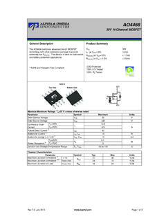
1 AO482860V dual N-Channel mosfets ymbolVDSVGSIDMIAR, IASEAR, EASTJ, JL3560 ARepetitive avalanche energy B18mJWJunction and Storage Temperature RangeAPD to 150TA=70 CIDC ontinuous DrainCurrent AFMaximumUnitsParameterTA=25 CTA=70 C60 Maximum Junction-to-Ambient Current B19 C/WAbsolute Maximum Ratings TA=25 C unless otherwise notedVV 20 Pulsed Drain Current BPower DissipationTA=25 CGate-Source VoltageDrain-Source VoltageMaximum Junction-to-Lead CSteady-State C/WThermal CharacteristicsParameterUnitsMaximum Junction-to-Ambient At 10sR JA C/WFeaturesVDS (V) = 60 VID = (VGS = 10V)RDS(ON) < 56m (VGS = 10V)RDS(ON) < 77m (VGS = )100% UIS tested100% Rg testedGeneral DescriptionThe AO4828 uses advanced trench technology toprovide excellent RDS(ON) and low gate charge.
2 Thisdevice is suitable for use as a load switch or in Top ViewSOIC-8 Top View Bottom ViewPin1 Alpha & Omega Semiconductor, C5 IGSS100nAVGS(th) (ON)20A4656TJ=125 C801006477m Qg(10V) ( ) (on) (off) PRODUCT HAS BEEN DESIGNED AND QUALIFIED FOR THE CONSUMER MARKET. APPLICATIONS OR USES AS CRITICAL COMPONENTS IN LIFE SUPPORT DEVICES OR SYSTEMS ARE NOT AUTHORIZED. AOS DOES NOT ASSUME ANY LIABILITY ARISINGOUT OF SUCH APPLICATIONS OR USES OF ITS PRODUCTS. AOS RESERVES THE RIGHT TO IMPROVE PRODUCT DESIGN,FUNCTIONS AND RELIABILITY WITHOUT NOTICEVGS=10V, VDS=30V, ID= Gate ChargeGate Drain ChargeVGS=0V, VDS=30V, f=1 MHzSWITCHING PARAMETERST otal Gate ChargeGate Source ChargeGate resistanceInput CapacitanceOutput CapacitanceTurn-On Rise TimeTurn-Off DelayTimeVGS=10V, VDS=30V, RL= ,RGEN=3 Turn-Off Fall TimeTurn-On DelayTimeVGS=0V, VDS=0V, f=1 MHzm VGS= , ID=3 AIS=1A,VGS=0 VVDS=5V, ID= PARAMETERSP ulsed Body Diode Current BMaximum Body-Diode Continuous CurrentRDS(ON)
3 Static Drain-Source On-ResistanceForward TransconductanceDiode Forward VoltageIDSS AGate Threshold VoltageVDS=VGS ID=250 AVDS=60V, VGS=0 VVDS=0V, VGS= 20 VZero Gate Voltage Drain CurrentGate-Body leakage currentElectrical Characteristics (TJ=25 C unless otherwise noted)STATIC PARAMETERSP arameterConditionsBody Diode Reverse Recovery TimeBody Diode Reverse Recovery ChargeIF= , dI/dt=100A/ sDrain-Source Breakdown VoltageOn state drain currentID=250 A, VGS=0 VVGS=10V, VDS=5 VVGS=10V, ID= Transfer CapacitanceIF= , dI/dt=100A/ sA: The value of R JA is measured with the device mounted on 1in 2 FR-4 board with 2oz. Copper, in a still air environment withT A=25 C. The value in any given application depends on the user's specific board : Repetitive rating, pulse width limited by junction The R JA is the sum of the thermal impedence from junction to lead R JL and lead to The static characteristics in Figures 1 to 6 are obtained using <300 s pulses, duty cycle These tests are performed with the device mounted on 1 in 2 FR-4 board with 2oz.
4 Copper, in a still air environment with T A=25 C. TheSOA curve provides a single pulse The current rating is based on the t 10s junction to ambient thermal resistance : May 2010 Alpha & Omega Semiconductor, ELECTRICAL AND THERMAL CHARACTERISTICS05101520012345 VDS (Volts)Fig 1: On-Region CharacteristicsID (A)VGS= (Volts)Figure 2: Transfer CharacteristicsID(A)20304050607080901000 5101520ID (A)Figure 3: On-Resistance vs. Drain Current andGate VoltageRDS(ON) (m ) + + (Volts)Figure 6: Body-Diode CharacteristicsIS (A)25 C125 ( C)Figure 4: On-Resistance vs. JunctionTemperatureNormalized On-ResistanceVGS=10 VVGS= (Volts)Figure 5: On-Resistance vs. Gate-Source VoltageRDS(ON) (m )25 C125 CVDS=5 VVGS= C125 CAlpha & Omega Semiconductor, ELECTRICAL AND THERMAL CHARACTERISTICS0246810012345678910Qg (nC)Figure 7: Gate-Charge CharacteristicsVGS (Volts)02004006008000102030405060 VDS (Volts)Figure 8: Capacitance CharacteristicsCapacitance (pF) Width (s)Figure 10: Single Pulse Power Rating Junction-to-Ambient (Note E)Power (W) Width (s)Figure 11: Normalized Maximum Transient Thermal ImpedanceZ JA Normalized TransientThermal (Volts)ID (Amps)Figure 9: Maximum Forward Biased SafeOperating Area (Note E)100 (Max)=150 CTA=25 CRDS(ON)limitedVDS=30 VID= PulseD=Ton/TTJ,PK=TA+ JAR JA= C/WTonTPDIn descending orderD= , , , , , , single pulseTJ(Max)=150 CTA=25 C10 sAlpha & Omega Semiconductor.