Transcription of Ultra High Precision Z-Foil Power Current Sensing …
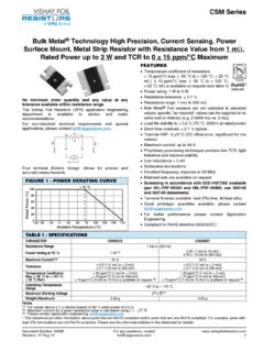
1 Ultra High Precision Z-Foil Power Current Sensing resistor with absolute TCR of ppm/ C, ESD Immunity up to 25 kV and Tolerance of %, Power Rating up to 2 WIMPROVED PRODUCTVCS232Z ( Z-Foil )Vishay Foil Resistors Document Number: 63095 For any questions, contact: 23-Mar-101 INTRODUCTIONT oday, designers of analog circuits are demandingdiscrete Power Current sense resistors that approach theideal in performance .. stable, high speed, high accuracycomponents that will operate with assured, predictablereliability for years in a variety of environments. Foil ismeeting those demands with the VCS232Z of four fundamental factors determine how ideal aprecision Power Current sense resistor will be:1.
2 Initial resistance value or how closely the absoluteresistance value can be achieved2. How precisely the value of individual resistors can becontrolled3. How precisely the end of life tolerance is maintainedunder a wide range of operating conditions and stressfactors (temperature, humidity, load, etc.)4. Fast response without ringing and fast thermalstabilization - and the ability of the resistor to react torapid switching without adversely affecting the the development of Foil resistors, precise control of allfour factors was virtually VCS232Z resistor containing the latest version of Z-foilachieves maximum stability, a near zero temperaturecoefficient and the ability to remove errors due totemperature gradients.
3 This superior performance is built-infor every unit and does not rely on culling or other artificialmeans for uniform (1)- 55 C to + 125 C, + 25 C ref. Contact applications engineering for other available valuesFEATURES Temperature coefficient of resistance (TCR): ppm/ C typical (0 C to 60 C) ppm/ C typical (- 55 C to + 125 C,+ 25 C ref.) Power coefficient R due to self heating :4 ppm/W typical Power rating at + 25 C: 2 W (free air) Tolerance: to % Load life stability: to %, 25 C for 2000 h at ratedpower Maximum Current : 3 A Resistance range: to 500 Foil resistors are not restricted to standard values; specific as required values can be supplied at no extra cost ordelivery ( vs.)
4 100 ) Electrostatic discharge (ESD) up to 25 000 V Short time overload % Non inductive, non capacitive design Rise time: 1 ns effectively no ringing Thermal stabilization time < 1 s Current noise < - 40 dB Thermal EMF: V/ C Voltage coefficient < ppm/V Non inductive: H Non hot spot design Terminal finish: lead (Pb)-free or tin/lead alloy Compliant to RoHS directive 2002/95/EC For better performances please contact us Prototype quantities available in just 5 working daysor sooner. For more information, please Automatic test equipment (ATE) High Precision instrumentation Electron beam application Medical Current Sensing applications Pulse applications Military Power amplifier Power supplies* Pb containing terminations are not RoHS compliant, exemptions may applyTABLE 1 - TOLERANCE AND TCRRESISTANCE RANGE( )TIGHTEST RESISTANCE TOLERANCETYPICAL TCR AND MAX.
5 SPREAD (ppm/ C) (1) to < 10 % to 500 % 1 - Power DERATING CURVE(Further Derating Not Necessary) + 100+ 75+ 50+ 250 - 50 0 + 50 + 100 + 150 + 200 Ambient Temperature ( C)f o t n e c r e P r e w o P d e t a R - 55 C+ 25 CI1E1E2I2 RVIIIMPROVED PRODUCTVCS232Z ( Z-Foil )Vishay Foil Resistors any questions, contact: Number: 630952 Revision: 23-Mar-10 FIGURE 2 - TRIMMING TO VALUES (conceptual illustration)Mutual InductanceReduction dueto Change inCurrent DirectionCurrent PathBefore TrimmingNote: Foil shown in black, etched spaces in whiteInterloop CapacitanceReduction in SeriesTrimming ProcessRemoves this Materialfrom Shorting Strip AreaChanging Current Pathand IncreasingResistanceCurrent PathAfter TrimmingFIGURE 3 - TYPICAL RESISTANCE/ TEMPERATURE CURVE (for more details, see table 1)+ 500 + 200 + 100 0 - 100 - 200 - 300 - 500 - 55- 25+ 25+ 60 + 75+ 100 + 125 Ambient Temperature ( C) and TCR Chord Slopes forDifferent Temperature Ranges R R (ppm) ppm/ C - ppm/ ppm/ C ppm/ C ppm/ C - ppm/ C - 400 + 300 + 400 FIGURE 4 - DIMENSIONS in inches (millimeters) ( )LT ( ) ( ) ( ) ( ) ( ) ( ) ( ) ( )
6 ( )TABLE 2 - VCS232Z PERFORMANCE SPECIFICATIONSTEST(Conditions per MIL-PRF-49465)CONDITIONSMIL-PRF-49465C R LIMITSTYPICAL R LIMITSMAXIMUM R LIMITST hermal Shock- 55 C to + 125 C, 5 cycles ( % + ) % %Short Time Overload5 x rated Power for 5 s ( % + ) % %Resistance to Soldering Heat10 s to 12 s at + 260 C ( % + ) % %Terminal StrengthPull test at 5 lb ( % + ) % %High Temperature Exposure2000 h, + 150 C ( % + ) % %Low Temperature StorageMIL-PRF-49465, 24 h at - 55 C ( % + ) % %Moisture ResistanceMIL-STD-202, method 106, + 65 C to - 10 C, 90 % to 98 % RH, rated Power , 240 h ( % + ) % %Shock (Specified Pulse)100 g, 6 ms ( % + ) % %Vibration (High Frequency)(10 Hz to 2000 Hz) 20 g ( % + ) % %Load Life Stability2000 h, + 25 C at rated Power ( % + ) % %SolderabilityMIL-STD-20295 % coverage--LT H L W LL D 1 LS D 2 Tin/Lead or Lead (Pb)-freeSolder coated copper leads IMPROVED PRODUCTVCS232Z ( Z-Foil )Vishay Foil Resistors Document Number: 63095 For any questions, contact: 23-Mar-103 POST MANUFACTURING OPERATIONS OR PMO FOR IMPROVED EOLMany analog applications can include requirements forperformance under conditions of stress beyond the norm andover extended periods of time.
7 This calls for more than justselecting a standard device and applying it to a circuit . Thestandard device may turn out to be all that is needed but ananalysis of the projected service conditions should be madeand it may well dictate a routine of stabilization known aspost manufacturing operations or PMO. The PMO operationsthat will be discussed are only applicable to Bulk Metal Foilresistors. They stabilize Bulk Metal Foil resistors while theymay be harmful to other types. Short time overload,accelerated load life, and temperature cycling are the threePMO methods that do the most to remove the anomaliesdown the road.
8 Bulk Metal Foil resistors are inherently stableas manufactured. These PMO methods are only of value onBulk Metal Foil resistors and they improve the performanceby small but significant amounts. Users are encouraged tocontact Foil applications engineering for assistance inchoosing the PMO operations that are right for (1)For non-standard requests, please contact application 3 - GLOBAL PART NUMBER INFORMATION (1)NEW GLOBAL PART NUMBER: Y160845R2361Q9L (preferred part number format)DENOTES PRECISIONVALUECHARACTERISTICSYR = 0 = standard9 = lead (Pb)-free1 to 999 = customPRODUCT CODERESISTANCE TOLERANCEPACKAGING1608 = VCS232ZQ= %A= %B= %D= %F= %G= %J= %L = bulkFOR EXAMPLE: ABOVE GLOBAL ORDER Y1608 45R2361 Q 9 L:TYPE: VCS232 ZVALUES: absolute TOLERANCE: %TERMINATION.
9 Lead (Pb)-freePACKAGING: bulk packHISTORICAL PART NUMBER: VCS232ZT 45R2361 Q B (will continue to be used) VALUETCR CHARACTERISTICABSOLUTE TOLERANCEPA C K A G I N GVCS232ZT = lead (Pb)-freeNone = Q = %A= %B= %D= %F= %G= %J= %B = bulk6084R235Y1Q96L1 Vishay Precision Group, Disclaimer NoticeDocument No.: 63999 Revision: 15-Jul-2014 DisclaimerALL PRODUCTS, PRODUCT SPECIFICATIONS AND DATA ARE SUBJECT TO CHANGE WITHOUT Precision Group, Inc., its affiliates, agents, and employees, and all persons acting on its or their behalf (collectively, VPG ), disclaim any and all liability for any errors, inaccuracies or incompleteness contained herein or in any other disclosure relating to any product specifications do not expand or otherwise modify VPG s terms and conditions of purchase, including but not limited to, the warranty expressed makes no warranty, representation or guarantee other than as set forth in the terms and conditions of purchase.
10 To the maximum extent permitted by applicable law, VPG disclaims (i) any and all liability arising out of the application or use of any product, (ii) any and all liability, including without limitation special, consequential or incidental damages, and (iii) any and all implied warranties, including warranties of fitness for particular purpose, non-infringement and provided in datasheets and/or specifications may vary from actual results in different applications and performance may vary over time. Statements regarding the suitability of products for certain types of applications are based on VPG s knowledge of typical requirements that are often placed on VPG products.