Transcription of AN126 - 2-Wire Virtual Remote Sensing for Voltage ...
1 Application Note 126AN126-1an126faOctober 20102-Wire Virtual Remote Sensing for Voltage RegulatorsClairvoyance Marries Remote SensingJim Williams, Jesus Rosales, Kurk Mathews, Tom HackL, LT, LTC, LTM, Linear Technology and the Linear logo are registered trademarks and Virtual Remote Sense is a trademark of Linear Technology Corporation. All other trademarks are the property of their respective and connectors have resistance. This simple, un-avoidable truth dictates that a power source s Remote load Voltage will be less than the source s output Voltage . Figure 1 shows this, and implies that intended load Voltage can be maintained by raising regulator output.
2 Unfortunately, line resistance and load variations introduce uncertainties, limiting achievable performance. Figure 2 illustrates one compensatory approach. Locally positioned regulation stabilizes load Voltage against line drops but is ineffi cient due to regulator losses. Figure 3, the classical approach, utilizes 4-wire Remote Sensing to eliminate line drop effects. The power supply sense inputs are fed from load referred sense wires. The sense inputs are high impedance, negating sense line resistance effects. This scheme works well, but requires dedicated sense wires, a signifi cant disadvantage in many applications.
3 Virtual Remote SensingFigure 4 retains the advantages of classical 4-wire re-mote Sensing while eliminating the sense leads. Here, the LT4180 Virtual Remote Sense (VRS) IC alternates output current between 95% and 105% of the nominal required output current. The LT4180 forces the power supply to provide a DC current plus a small square wave current with peak-to-peak amplitude equal to 10% of the DC current. Decoupling capacitor CLOAD, normally required for low impedance under transient conditions in non-VRS systems, takes an additional role by fi ltering out the VRS square wave excursions.
4 AN125 F01 POWERSUPPLYLOADWIRING DROPSWIRING DROPSAN125 F02 POWERSUPPLYLOADVOLTAGEREGULATORLOADF igure 1. Unavoidable Wiring Drops Cause Low Load Voltage . Line and Load Resistance Variations Introduce Additional Load Voltage Uncertainty, Mitigating Against Compensation by Raising Supply VoltageFigure 2. Local Regulation Stabilizes Load Voltage But is Ineffi cientAN125 F03 POWERSUPPLYLOADVOUT+SENSE+SENSE VOUT Voltage DROPRWIREVOLTAGE DROPRWIREF igure 3. Classical 4-Wire Remote Sensing . VOUT Line Voltage Drops Are Compensated by Regulator Sensing at Load. High Impedance Sense Inputs Negate Sense Wire Resistance.
5 Approach Requires Four WiresAN125 F04 POWER SUPPLYCONTROL PINVOUTVLILCLOADVOUT = DC + SQUAREWAVE FROM WIRING Voltage DROPCLOAD REMOVES SQUAREWAVE, SO VL CONTAINS ONLY = DC + SQUAREWAVERWIRE/2 ISENSERWIRE/2+ LOAD+ LT4180 Figure 4. LT4180 2-Wire Virtual Remote Sense Estimates Wiring Voltage Drops, Compensates by Adjusting Supply Output Voltage . Wiring Loss Is Determined by Measuring Small Signal Square Wave Carrier Induced Voltage Drop. Load Capacitor Absorbs Square Wave; Load Is at DCApplication Note 126AN126-2an126faBecause C is sized to produce an AC short at the square wave frequency, a square wave Voltage is produced at the power supply equal to VOUTAC = IDC RWIREVP-P.
6 The square wave Voltage at the power supply has a peak-to-peak amplitude equal to one tenth the DC wiring drop. This is a direct measurement of wiring drop, not an estimate, accurate over all load currents. Signal processing produces a DC Voltage from this AC signal which is introduced into the supply feedback loop to provide accurate load regula-tion1. Note that the power supply may be an IC linear or switching regulator, a module or any other power source capable of variable output. Power supplies can be syn-chronized to the LT4180 and VRS operating frequency is adjustable over more than three decades.
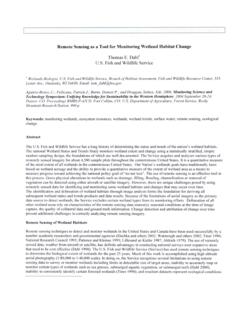
7 Optional spread spectrum operation provides partial immunity from single-tone interference and a 3V to 50V input range simplifi es design. Because this technique is based on an estimate of load Voltage , not a direct measurement, the resultant correction is an approximation, but a very good one. Typical LT4180 load regulation is plotted in Figure 5. In this example, load current increases from zero until it produces a wiring drop. Load Voltage drops only 73mV at maximum current. A Voltage drop equivalent to 50% of load Voltage results in only a shift in load Voltage value. Smaller wiring drops produce even better results.
8 ApplicationsThe following applications are all VRS augmented Voltage regulators of various descriptions. The power regulation stages employed are, with one exception, generic LTC designs and are spared exhaustive commentary, permit-ting emphasis on the LT4180 VRS role. Additionally, the similarity of the VRS associated circuitry across the broad array of applications shown should be noted, and is indica-tive of the relative ease of implementation. Surprisingly little change is needed to use the VRS in the different situations presented. VRS Linear RegulatorsFigure 6 adds a simple stage to the LT4180 to implement a complete VRS aided linear regulator.
9 The LT4180 senses current via the shunt and feedback controls Q1 with Q2, completing a control loop. Cascoded Q2 permits the ICs 5V capable open drain output to control a high Voltage at Q1 s gate. Components at the compensation pin furnish loop stability, promoting good transient response2. Figure 7 shows Figure 6 s load step waveforms. They include VSENSE (trace A), VLOAD (B) and ILOAD (C). Transient response is determined by loop compensation, load capacitance and Remote sense sample rate. Figure 8 shows response with CLOAD increased to 1100 F. Load Voltage transient excur-sion reduces and duration increases.
10 Figure 9, employing a monolithic regulator, adds current limiting and simplifi es loop compensation. Transient re-sponse approximates Figure 6 s. As before, the LT4180 s low Voltage drain pin requires a cascode transistor to control the high Voltage at the LT3080 set pin. VWIRING (V)0 VLOAD (V) F05 Figure 5. Typical LT4180 Virtual Remote Sense Performance Shows Regulation vs 0V Wiring DropNote 1. Readers fi nding their intellectual prowess unsatiated by this admittedly cursory description will fi nd more studious coverage in Appendix A, A Primer on LT4180 VRS Operation. Note 2. Value selection procedure for LT1480 VRS circuits is detailed in Appendix B, Design Guidelines for LT4180 VRS Circuits.