Transcription of Gauge Installation Instructions - Vehicle Controls, LLC
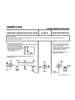
1 TEMPERATURE, PRESSURE AND fuel LEVEL GAUGES Gauge Installation Instructions RUDDER POSITION INDICATOR D. Due to the variety of steering systems, we do not include any linkage parts without rudder senders. However, our mounting kit provides the necessary parts for most applications. Please check with your dealer. E. For dual station Installation wire two gauges parallel to sender. VOLTMETER D. Temperature and Pressure Senders Remove blind plug or existing warning light switch from engine/gearbox (If applicable). Install sender instead. Cut 2- 5/16" hole in tank. Make sure float movement will not be obstructed. Remove all metal burrs. Adjust sender length (L) and float radius (R): L= 1/2 H, R" 2/3 H. E. For dual station Installation use dual sending unit and wire two gauges in parallel.
2 0-511-011-063 A. Disconnect battery. B. Cut 2- 3/32" hole in a suitable position in dash. Make sure rear of instrument has sufficient clearance from existing equipment and wiring. C. Wire Gauge according to diagram. Engine Hour Meter Quartz Clock Power Trim Gauge D. For electrical connection of sender unit refer to power trim manufacturer instruction (owners manual) D. Positive Gauge terminal must be connected to +12 V only if engine is running ( ignition switch, pressure switch) If you should not get proper readings from Siemens VDO Gauge : DO NOT attempt to open, as this voids any warranty! Check wiring, especially for proper ground. All gauges are floating grounds: you have to run a separate ground connection from terminal "- " to ground. If sender is standard ground, make sure the engine/gearbox has common ground, is grounded to same battery negative as gauges.
3 In case of sender being floating ground, ground terminal has to be connected to Gauge negative. Not for Voltmeter, Engine Hour Meter and Quartz Clocks: Pull sender lead from sending unit. Pointer must now move fully to one side of scale. Then, ground sender lead. Pointer must now peg to opposite side of scale. If both occurs, your Gauge and wiring is basically , the problem will be a defective or improperly grounded sending unit. Siemens VDO Instruments are repairable. D. Positive Gauge Terminal must be connected 12 V source. ALLENTOWN, PA USA 1- 800- 265- 1818 Permanent +12V Dash Light Switch A. Disconnect battery. B. Cut 2 - 3/32" hole in a suitable position in dash. Make sure rear of instrument has sufficient clearance from existing equipment and wiring. C. Wire Gauge according to diagram. to unswitchedSiemens VDO Limited WarrantyVDO North America warrants all merchandise against defects in factory workmanship and materials for a period of 24 months after purchase.
4 Thiswarranty applies to the first retail purchaser and covers only those products exposed to normal use or service. Provisions of this warranty shall notapply to a VDO product used for a purpose for which it is not designed, or which has been altered in any way that would be detrimental to theperformance or life of the product, or misapplication, misuse, negligence or accident. On any part or product found to be defective after examinationby VDO North America, VDO North America will only repair or replace the merchandise through the original selling dealer or on a direct basis. VDON orth America assumes no responsibility for diagnosis, removal and/or Installation labor, loss of Vehicle use, loss of time, inconvenience or any otherconsequential expenses. The warranties herin are in lieu of any other expressed or implied warranties, including any implied warranty of merchant-ability or fitness, and any other obligation on the part of VDO North America, or selling dealer.
5 (NOTE: This is a Limited Warranty as defined by the Magnuson-Moss Warranty Act of 1975.)Siemens VDO . Phone: 1-800-265-1818 Mechanical Dual Air Pressure GaugeInstallation InstructionsInstruction Sheet #0 515 010 389 Rev. 07/03 Instructions FOR THE Installation OF THE MECHANICAL DUAL AIR PRESSURE GAUGEARE CONTAINED HEREIN. LIGHT BULB SUPPLIED IS 24 VDOTo Begin, go to # The bezel diameter is only a few mil-limeters larger than the Gauge that in mind, measure and pre-cisely mark the Gauge location be-fore cutting any holes!CAUTION!!! Air Pressure Gauge (3 " [80 mm] diameter) Bulb (24 volt) Mounting Brackets and Instructions1 Parts ListYour VDO mechanical dual air pressuregauge comes with a 24volt bulb standard; for12 volt operation, order VDO bulb number600 802. These instruments require a tubingkit to complete Installation .
6 MAKE SURETHAT THE TUBING USED IS RATEDFOR 150 PSI OR Information:1. Select the location where you will mountthe Gauge , and mark a center point for ahole .2. Cut a 3 " (80 mm) diameter hole for thepressure Gauge . Place the instrument intothe hole. If the Gauge is too snug, use a file toslightly enlarge the opening until the gaugefits properly. See Diagram Slip a mounting bracket over each mount-ing bolt on the back of the Gauge . Screw onthe accompanying nuts. Tighten the nutsuntil the Gauge can no longer be rotated byhand. DO NOT OVERTIGHTEN! Gauge Installation :Use " outside diameter tubing. You willalso need a ferrule and a sealing nut, whichare readily available from your auto and Materials Needed For Installation :16 Gauge stranded, insulated wireInsulated " spade connectors3 " hole sawDrill and drill bit setHalf-round fileTape measure or rulerSmall tools: wrench or nut driver, utility knife,pliers, kit and various engine adaptersDiagram AGauge Dimensions!
7 !( # ]]! "&]]! " # %]]BUT 4_dGXYdU 4_d# (%]]( ]]# ($]]# # CAUTION: Read these instructionsthoroughly before beginning Installation . Do notdeviate from assembly or wiring disconnect battery ground before makingany electrical you have any doubts, please contact yourdealer or VDO Instruments at BGauge hookup and lamp wiring information1. Route the tubing from the Gauge to the airline. DO NOT CRIMP the tubing closedduring routing. A rubber grommet is recom-mended around each tube where it passesthrough the Attach one end of each tube to the gaugeusing a "-24 UNS-2A adapter. You mustalso use a ferrule and sealing nut, as shownGauge Hookup and Lamp Wiring:in Diagram NOT OVERTIGHTEN THE SEAL-ING NUTS OR YOU WILL DAMAGETHE TUBING!3. Attach the other end of each tube to itscorresponding air line using appropriate teesand fittings.))))
8 A white dot indicates the "pri-mary" air line; a red dot, the "secondary."4. Run a wire from the Gauge lamp socket tothe lighting circuit (a +24 volt source, usu-ally after the light switch fuse). For +12voperation, use 12v bulb (VDO #600 802). Ifthe Gauge housing is not grounded, run aground wire to one of the mounting Diagram this point, Installation is :Make sure the tubes are absolutely freefrom moving and/or hot engine com-ponents, and that it is totally free the engine and turn on the lights tomake sure the Gauge illumination functionsproperly. If it doesn't, recheck your con-nections and your wiring. Check all tub-ing connections for ^W ]ecd RUbQdUT V_b !% @C9_b WbUQdUb \U^WdX fQbYUc CUQ\Y^W>ed6 Ubbe\U@bUccebU7 QeWU 816 $ EXVKLQJ<YWXd C_S[Ud2 QddUbi7b_e^T<YWXdCgYdSX6ecU2_h7b_e^T d_]_e^dY^W cdeT=_e^dY^W cdeT"$f Re\R V_b !
9 "f ecU ` ^ & ( ")White Pointer = Primary AirRed Pointer = Secondary AirInstrument Kit Installation and Wiring InstructionsSiemens VDOA llentown, Pennsylvania USA USE IS RESTRICTED TO 12 VOLT NEGATIVE GROUND ELECTRICAL #0 515 010 396 Rev. 09/03 ItemDescription CAUTION: Read these Instructions thoroughly before mak-ing Installation . Do not deviate from assembly or wiring in-structions. Always disconnect battery ground before makingany electrical connections. If in doubt, please contact yourdealer or VDO Instruments at Information:These kits come with VDO s Spin-Lok Mounting Clamps for easyinstallation. Optional VDO mounting brackets are available fromyour VDO dealer, should you require them. Note that the pro-grammable speedometer included in this kit has a special set of in-stallation and operation Instructions . These Instructions must befollowed carefully to insure proper performance of the Installation :Diagram AProper mounting using VDO s Spin-Lok Mounting ClampMinimum mounting depth2 7/8" (73mm)Speedometer Installation :PLEASE REFER TO THE SEPARATE PROGRAMMABLESPEEDOMETER Installation AND OPERATINGINSTRUCTIONS FOR PROPER MOUNTING AND OP-ERATION OF THE SPEEDOMETER.
10 SEE PAGE 3 FORINSTRUCTIONS ON INSTALLING SPEED Speedometer (3 1/8" or 3 3/8" diameter) (21/16" diameter Gauge (21/16" diameter) Gauge (21/16" diameter) Gauge (21/16" diameter) Sender (1/8" 27 NPT) Sender (3/8" 18 NPT) 18. fuel Level Sender & Float Arm 193/8"-18 NPT to 1/2"-14 NPT adapter Sensor, Hall Effect 111. Spin-Lok Mounting Clamp for gauges and speedometer Kit Installation Instruction Programmable Installation Instructions Harness (Millenimum Kit ONLY) 1 Parts List Additional Material That Maybe Required For Installation :16 Gauge stanard insulated wire (P/N: 240-023)Insulated female 1/4" spade terminalsGauge connectors for 2 1/16" Gauge (one per Gauge P/N: 240-026) Speedometer connector (P/N: 240-053) fuel Sender Bolt on Installation Kit ( P/N: 226-451) fuel Sender Weld on Installation Kit ( P/N: 226-901)Stud Mounting Kits 2 1/16" gauges ( P/N: 600-402)Stud Mounting Kit, Speedometer ( P/N: 600-401) fuel Sender Ford application: 1935-1956 ( P/N: 226-902) 1.)