Transcription of 0.1 GHz to 6.0 GHz,0.5 dB LSB, 6-Bit, GaAs Digital ...
1 GHz to GHz, dB LSB, 6-Bit, gaas Digital Attenuator data sheet hmc624a . FEATURES FUNCTIONAL BLOCK DIAGRAM. D0. D1. D2. D3. D4. D5. Attenuation range: dB (LSB) steps to dB. 24 23 22 21 20 19. Low insertion loss: dB at 3 GHz Excellent attenuation accuracy P/S 1 18 VDD. High linearity CLK 2 17 PUP1. Input compression ( ): 33 dBm typical SERIAL/. PARALLEL. Input third-order intercept (IP3): 55 dBm typical SERIN 3 INTERFACE 16 PUP2. High RF input power handling: 28 dBm LE 4 15 SEROUT. Low phase shift: 25 at 3 GHz Single-supply operation: 3 V to 5 V 6-BIT/. GND 5 Digital 14 GND. CMOS-/TTL-compatible control ATTENUATOR. ATTIN 6 13 ATTOUT. 24-lead, 4 mm 4 mm LFCSP package Pin compatible to the HMC1122 7 8 9 10 11 12.
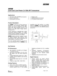
2 PACKAGE. ACG1. ACG2. ACG3. ACG4. ACG5. ACG6. 15353-001. APPLICATIONS BASE. GND. Cellular infrastructure Figure 1. Microwave radios and very small aperture terminals (VSATs). Test equipment and sensors Intermediate frequency (IF) and radio frequency (RF) designs GENERAL DESCRIPTION. The hmc624a is a 6-bit Digital attenuator with a dB serial output port for cascading other serial controlled attenuation control range in dB steps. components. The hmc624a offers excellent attenuation accuracy and high The hmc624a operates with a single positive supply voltage input linearity over the specified frequency range from 100 MHz from 3 V to 5 V, and provides a CMOS-/TTL-compatible to GHz. However, this Digital attenuator features external ac control interface.
3 Grounding capacitors to extend the operation below 100 MHz. The hmc624a comes in a RoHS compliant, compact, 4 mm . The hmc624a is integrated with two dies: a CMOS driver and 4 mm LFCSP package, and is pin compatible to the HMC1122. a gallium arsenide ( gaas ) RF attenuator. The CMOS driver except for the ACGx pins. provides both serial and parallel control of the RF attenuator. The device also features a user-selectable power-up state and a Rev. B Document Feedback Information furnished by analog devices is believed to be accurate and reliable. However, no responsibility is assumed by analog devices for its use, nor for any infringements of patents or other rights of third parties that may result from its use.
4 Specifications subject to change without notice. No One Technology Way, Box 9106, Norwood, MA 02062-9106, license is granted by implication or otherwise under any patent or patent rights of analog devices . Tel: 2017 analog devices , Inc. All rights reserved. Trademarks and registered trademarks are the property of their respective owners. Technical Support hmc624a data sheet TABLE OF CONTENTS. Features .. 1 Input Power Compression and Third-Order Intercept ..9. Applications .. 1 Theory of Operation .. 11. Functional Block Diagram .. 1 Power 11. General Description .. 1 Power-Up Interface .. 11. Revision History .. 2 Serial or Parallel Mode Selection .. 11. 3 Serial Mode Interface .. 11. Timing Specifications.
5 4 Parallel Mode Interface .. 12. Absolute Maximum Ratings .. 5 RF Input and Output .. 12. Thermal Resistance .. 5 ACGx Pins .. 12. ESD Caution .. 5 Applications Information .. 13. Pin Configuration and Function Descriptions .. 6 Evaluation Board .. 13. Interface 6 Outline Dimensions .. 15. Typical Performance Characteristics .. 7 Ordering Guide .. 15. Insertion Loss, Return Loss, State Error, Step Error, and Relative 7. REVISION HISTORY. 9/2017 Rev. A to Rev. B Changes to Figure 9, Figure 10, Figure 12, and Figure 13 ..7. Changed CP-24-2 to CP-24-16 .. Throughout Deleted Application Circuit Figure ..8. Changes to Table 3 .. 5 Added Figure 14, Figure 15, and Figure Updated Outline Dimensions .. 15 Changes to Figure 16.
6 8. Changes to Ordering Guide .. 15 Added Figure 20 and Figure 23 ..9. Changes to Figure 21 and Figure 22 ..9. 3/2017 Rev. to Rev. A Added Figure 26 and Figure 29 .. 10. This Hittite Microwave Products data sheet has been reformatted to Added Theory of Operation Section, Serial or Parallel Mode meet the styles and standards of analog devices , Inc. Selection Section, Table 8, and Figure 30 .. 11. Changes to Table 6, Power Supply Section, Power-Up Interface Changes to Title, Features Section, Applications Section, and Section, Table 7, Serial Mode Interface Section .. 11. General Description Section .. 1 Added RF Input and Output Section and AGCx Pins 12. Changes to Table 1 .. 3 Changes to Figure 31, Parallel Mode Interface Section, Direct Added Table 2; Renumbered Sequentially.
7 4 Parallel Mode Section, Latched Parallel Mode Section, and Changes to Table 3 .. 5 Figure 32 .. 12. Added Figure 2 and Thermal Resistance Section; Renumbered Added Applications Information Section .. 13. Sequentially .. 5 Changes to Evaluation Board 13. Deleted Bias Voltage Table and Control Voltage Table; Added Figure 34 .. 14. Renumbered 5 Changes to Table 14. Added Figure 6 Updated Outline Dimensions .. 15. Changes to Table 5 .. 6 Changes to Ordering Guide .. 15. Added Insertion Loss, Return Loss, State Error, and Relative Phase 7. Rev. B | Page 2 of 15. data sheet hmc624a . SPECIFICATIONS. VDD = 3 V to 5 V, control input voltage (VCTL) = 0 V or VDD, TCASE = 25 C, 50 system, unless otherwise noted. Table 1.
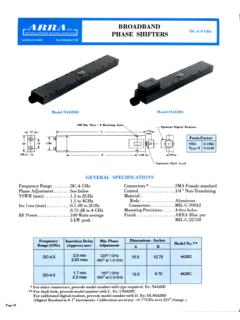
8 Parameter Symbol Test Conditions/Comments Min Typ Max Unit FREQUENCY RANGE GHz INSERTION LOSS GHz to 3 GHz dB. 3 GHz to GHz dB. ATTENUATION GHz to GHz Range Between minimum and maximum dB. attenuation states Step Size Between any successive dB. attenuation states Step Error Between any successive < dB. attenuation states State Error All attenuation states, referenced to insertion loss state GHz to GHz ( + 5% of +( + 5% of dB. attenuation state) attenuation state). GHz to GHz ( + 3% of +( + 3% of dB. attenuation state) attenuation state). RETURN LOSS (ATTIN and ATTOUT) All attenuation states, 15 dB. GHz to GHz RELATIVE PHASE Between minimum and maximum attenuation states 100 MHz to 3 GHz 25 Degrees 3 GHz to GHz 50 Degrees SWITCHING CHARACTERISTICS Between all attenuation states Rise and Fall Time tRISE, tFALL 10% to 90% of RF output 60 ns On and Off Time tON, tOFF 50% VCTL to 90% of RF output 90 ns INPUT LINEARITY 1 All attenuation states, 250 MHz to GHz dB Compression VDD = 3 V 33 dBm VDD = 5 V 27 dBm Third-Order Intercept IP3 VDD = 3 V to 5 V, 10 dBm per tone, 55 dBm 1 MHz spacing SUPPLY CURRENT IDD VDD = 3 V to 5 V 3 mA.
9 Digital CONTROL INPUTS P/S, CLK, SERIN, LE, D0 to D5, PUP1, and PUP2 pins Voltage Low VINL VDD = 3 V 0 V. VDD = 5 V 0 V. High VINH VDD = 3 V 2 3 V. VDD = 5 V 2 5 V. Current VDD = 3 V to 5 V. Low IINL 15 A. High IINH 65 A. Digital CONTROL OUTPUT SEROUT. Voltage Low VOUTL 0 V. High VOUTH VDD V. Current Low IOUTL 1 mA. High IOUTH 1 mA. 1. Input linearity performance degrades at frequencies less than 250 MHz; see Figure 18 to Figure 29. Rev. B | Page 3 of 15. hmc624a data sheet TIMING SPECIFICATIONS. See Figure 31 and Figure 32 for the timing diagrams. Table 2. Parameter Description Min Typ Max Unit tSCK Minimum serial period 70 ns tCS Control setup time 15 ns tCH Control hold time 20 ns tLN LE setup time 15 ns tLEW Minimum LE pulse width 10 ns tLES Minimum LE pulse spacing 630 ns tCKN Serial clock hold time from LE 0 ns tPH data hold time from LE 10 ns tPS data setup time to LE 2 ns Rev.
10 B | Page 4 of 15. data sheet hmc624a . ABSOLUTE MAXIMUM RATINGS. 2. Table 3. Parameter Rating 0. Supply Voltage V. POWER DERATING (dB). Digital Control Input Voltage 1 V to VDD + 1 V 2. RF Input Power1 (All Attenuation States, W. f = 250 MHz to GHz, TCASE = 85 C) 4. VDD = 3 V 25 dBm VDD = 5 V 28 dBm 6. Continuous Power Dissipation, PDISS W. (TCASE = 85 C) 8. Temperature Junction, TJ 150 C 10. 15353-002. Storage 65 C to +150 C 1. FREQUENCY (GHz). Reflow2 ((Moisture Sensitivity Level 1 260 C. (MSL1) Rating) Figure 2. Power Derating at Frequencies Less Than 250 MHz ESD Sensitivity THERMAL RESISTANCE. Human Body Model (HBM) 250 V (Class 1A). Thermal performance is directly linked to printed circuit board 1. For power derating at frequencies less than 250 MHz, see Figure 2.)