Transcription of 1 THE LIGHT BULB EXPERIMENT: Exploring Simple Electric ...
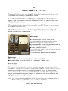
1 1 THE LIGHT BULB EXPERIMENT: Exploring Simple Electric CircuitsPreparatory Questions for Review:(also read this guide sheet, which contains some of the answers!)1. State Ohm s Law, defining every term in the If a bulb connected directly to a 6 V battery glows brightly when 1 A of current passesthrough it, what is the resistance of the bulb at that point? What is the power delivered to thebulb by the battery in this Two equal resistors are connected a) in series and b) in parallel . Write down the resistance ofthe combination in the two Read "Some electrical terms - a review" (next page). What is the electrical analogue ofpressure difference in the hydraulic model?Objectives: to develop facility in wiring Simple circuits to understand the concepts of electrical potentialdifference (voltage) and of electrical current to understand how voltage and current are divided upwhen circuit components are combined to draw schematic diagrams to use schematic diagrams as an aid to understandingwhat a circuit is doing to use schematic diagrams as an aid to wiringReferences: The introductory Electric circuits chapter of your first year textbook Lillian McDermott, Physics by Inquiry, Vol 2; John Wiley, Toronto, :This series of experiments enables you to test your understanding of the properties of electriccurrent flow.
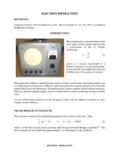
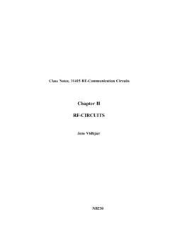
2 You will have available to you some small LIGHT bulbs, a battery (source ofconstant voltage), a current supply (source of constant current), a power supply of variablevoltage, meters to measure voltage and current, and lots of wires to connect all of these together. Since much of this lab is qualitative, be sure to write clear and concise notes on your procedure,and highlight those measurements you do make. 2 Figure 2 Figure 1 Notes:This experiment is mainly a qualitative one. Careful error analysis is notappropriate for the most part, but you should give quick estimates of electrical terms - a this section, in order that you better visualize what the electrical phenomena are, we will drawupon an hydraulic analogy - in other words, we will take a Simple Electric circuit , shown inFigure 1, of a battery connected by wires to an Electric motor, and compare it to an hydrauliccircuit, show in Figure 2 - of an upper water reservoir in which the water in it has previouslybeen taken from a lower tank to an elevated tank - connected by pipes to a paddle wheel motor.
3 (We hope to have a working model of this hydraulic analogue available to clarify thisexplanation).I = current in Coulombs/s (Amperes)(Note: the battery gets recharged prior to useby moving electrical charge from one batteryterminal to the other.) I = current in m3/s(Note: the hydraulic energy source getsrecharged prior to use when the water in thelower tank gets placed in the upper tank.)Notice that both the battery and the water tanks have stored energy, and after some use they bothrun down and no more energy is available from these : this is the electrical "size" of the electrical entities that are acting, as evidenced by theforce between two of these charges. Units are Coulombs (= electron charges). In ourhydraulic analogue its equivalent is volume of water = : this is the rate of flow of electrical charge through a device or wire ( flowing past apoint in the wire).
4 Units are Coulombs/second = Amperes. The hydraulic analogue is volumerate of flow of water = m3/second. 3 Potential difference or voltage: this has to do with the "push" on charges that the electricalforce has between two points in a circuit . More clearly, it is the difference in potential energythat a 1 Coulomb charge experiences in being transferred between the two points in the circuitthat are being compared. Units are Joules/Coulomb = Volts. The hydraulic analogue is pressuredifference = Pascal = that in both cases current flows through a wire or pipe whereas voltage (or pressuredifference) has to do with a difference between two points in wires or is left to you to conclude that in both the electrical and hydraulic cases, current flow betweenpoints in the circuit at different potentials implies transfer of power into/out of that region andthat the power transferred is just the current times the potential difference.
5 (Thus, both electriccircuits and hydraulic circuits are convenient media for transporting power.) A note about the equipment:The bulbs and power sources are reasonably inexpensive and not easily destroyed by wrongconnections. Also, the voltages used are so low that there is no danger of Electric shock. Thisallows you to try out any combination you wish without concern. The battery does have a"breaker" on it so that if too much current does get demanded from it, the breaker will open. Ifthat happens, merely disconnect the wire you had connected, wait a minute, and then push thebreaker's reset button. So we invite you to play with this equipment and to not worry aboutdamaging it. [EXCEPTION - PLEASE NOTE: When using the ammeter NEVER connect itdirectly across the battery, and, when you first introduce it into the circuit ensure that it is set onthe 20A selection.]
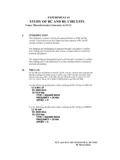
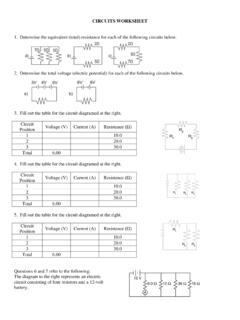
6 Read the CAUTIONS in the section on the ammeters at the end).The brightness of a bulb is proportional to the power delivered to it - the product of theresistance and the square of the current passing through it. The bulbs vary somewhat inconstruction and room-temperature resistance, and their resistance increases as they shine morebrightly. The bulbs shine at full brightness when the voltage across them is about 6 Volts so thatthey pass a current of about 1 Ampere. The battery supplies an approximately constant voltageof 6 use the following symbols in our schematic diagrams:What to do: Note: As a general guide, we expect that most students will be able to completeparts 1 through 5 or possibly 6 during the first session devoted to this experiment, and theremaining sections during the second 3 Figure 41.
7 The circuit : Use one bulb and one battery and a maximum of two wires. Note that both thebattery and the bulb have two connections each. Explore all the ways you can join (with one andwith two wires) the various connections to the battery and the bulb. Which ways make the bulblight? Which ways blow the breaker on the battery? Which ways do nothing? Does the order ofwhich end of the battery is connected, or of which end of the bulb is connected, make anydifference to your observations? Generalize what you find in terms of the concept of a closed Electric circuit or complete circuit . Describe what is happening from the point of view of the hydraulic analogue. Write down, inyour lab notebook, your successful circuit diagrams, your observations and generalizations. Ifyou don't know how to draw a schematic diagram of your circuit , ask your demonstrator.
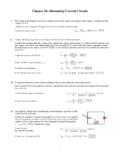
8 Canyou now define the terms open circuit and short circuit ?Some examples of configurations you might try are shown in Figure Lamps in series : The connection for two bulbs in series , connected to the battery, is shownin Figure 4. By series we mean that the two lamps are strung in a line, with one wire coming outof one lamp and going into one side of the next the circuit of Figure 4. From your observation of the brightness of the lamps, what canyou conclude about the current through each lamp compared to the case of the successful singlebulb and battery circuit of Figure 3? What can you say about the current through one lampcompared to that through the other in this configuration? We have heard students say that, withtwo lamps in series , the second lamp should get less current as the charge carriers (electrons)should get "tired" after going through the first.
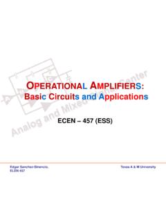
9 Do you agree? Comment on this statement,particularly in the LIGHT of the hydraulic analogue. With the circuit of Figure 4, try taking anextra wire and connecting it across the two terminals of one lamp. What happens to that lamp? What happens to the other lamp? 5 Figure 5[Note: before using the meter as an ammeter, see the instructions for its usein Appendix 1; use only the 20A range in this experiment]Now, with the circuit of Figure 4, measure the current into and out of each lamp, using yourmeters as ammeters. Comment on the three values you can measure - between the "+" batteryterminal (red) and a bulb, between the two bulbs, and between the a bulb and the "-" batteryterminal (black). Do the numbers you observe agree with your conclusions? Now, with the circuit of Figure 4, measure the voltage across each of the lamps separately, usinga meter as a voltmeter.
10 Also measure the voltage across the battery. What can you say about theway the voltage distributes itself across these identical lamps in series ?Repeat the "lamps in series " observations above with three lamps in series instead of two, andwrite down your Lamps in parallel : The connection for two bulbs in parallel , connected to the battery, isshown in Figure 5. By parallel we mean that the lamps are connected side-by-side, withcorresponding sides of both lamps connected the circuit of Figure 5. From your observation of the brightness of the lamps, what canyou conclude about the current through each lamp compared to the case of the single bulb andbattery circuit ? Now, with the circuit of Figure 5, measure the current into and out of each lamp, and the currentout of the battery. How do these currents appear to be related?