Transcription of Fundamentals of Direct Current Circuits - CED Engineering
1 Fundamentals of Direct Current Circuits Course No: E06-001 Credit: 6 PDH A. Bhatia Continuing Education and Development, Inc. 9 Greyridge Farm Court Stony Point, NY 10980 P: (877) 322-5800 F: (877) 322-4774 3-1 CHAPTER 3 Direct CURRENTLEARNING OBJECTIVESUpon completing this chapter, you will be able to:1. Identify the term schematic diagram and identify the components in a circuit from a simpleschematic State the equation for Ohm s law and describe the effects on Current caused by changes in Given simple graphs of Current versus power and voltage versus power, determine the value ofcircuit power for a given Current and Identify the term power, and state three formulas for computing Compute circuit and component power in series , parallel , and combination Compute the efficiency of an electrical Solve for unknown quantities of resistance, Current .
2 And voltage in a series Describe how voltage polarities are assigned to the voltage drops across resistors whenKirchhoff s voltage law is State the voltage at the reference point in a Define open and short Circuits and describe their effects on a State the meaning of the term source resistance and describe its effect on a Describe in terms of circuit values the circuit condition needed for maximum power Compute efficiency of power transfer in a Solve for unknown quantities of resistance, Current , and voltage in a parallel State the significance of the polarity assigned to a Current when using Kirchhoff s Current State the meaning of the term equivalent Compute resistance, Current , voltage, and power in voltage Describe the method by which a single voltage divider can provide both positive and Recognize the safety precautions associated with the hazard of electrical Identify the first aid procedures for a victim of electrical material covered in this chapter contains many new terms that are explained as you progressthrough the material.
3 The basic dc circuit is the easiest to understand, so the chapter begins with the basiccircuit and from there works into the basic schematic diagram of that circuit . The schematic diagram isused in all your future work in electricity and electronics. It is very important that you become familiarwith the symbols that are chapter also explains how to determine the total resistance, Current , voltage, and power in aseries, parallel , or combination circuit through the use of Ohm s and Kirchhoff s laws. The voltage dividernetwork, series , parallel , and series - parallel practice problem Circuits will be used for practical examplesof what you have BASIC ELECTRIC CIRCUITThe flashlight is an example of a basic electric circuit . It contains a source of electrical energy (thedry cells in the flashlight), a load (the bulb) which changes the electrical energy into a more useful formof energy (light), and a switch to control the energy delivered to the you study a schematic representation of the flashlight, it is necessary to define certain LOAD is any device through which an electrical Current flows and which changes this electricalenergy into a more useful form.
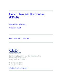
4 Some common examples of loads are a lightbulb, which changeselectrical energy to light energy; an electric motor, which changes electrical energy into mechanicalenergy; and the speaker in a radio, which changes electrical energy into sound. The SOURCE is thedevice which furnishes the electrical energy used by the load. It may consist of a simple dry cell (as in aflashlight), a storage battery (as in an automobile), or a power supply (such as a battery charger). TheSWITCH, which permits control of the electrical device, interrupts the Current delivered to the REPRESENTATIONThe technician s main aid in troubleshooting a circuit in a piece of equipment is the SCHEMATICDIAGRAM. The schematic diagram is a "picture" of the circuit that uses symbols to represent the variouscircuit components; physically large or complex Circuits can be shown on a relatively small studying the basic schematic, look at figure 3-1.
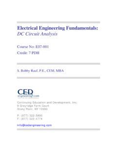
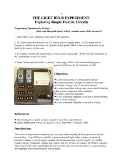
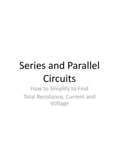
5 This figure shows the symbols that are used inthis chapter. These, and others like them, are referred to and used throughout the study of electricity 3-1. Symbols commonly used in schematic in figure 3-2 represents a flashlight. View A of the figure shows the flashlight in theoff or deenergized state. The switch (S1) is open. There is no complete path for Current (I) through thecircuit, and the bulb (DS1) does not light. In figure 3-2 view B, switch S1 is closed. Current flows in thedirection of the arrows from the negative terminal of the battery (BAT), through the switch (S1), throughthe lamp (DS1), and back to the positive terminal of the battery. With the switch closed the path forcurrent is complete. Current will continue to flow until the switch (S1) is moved to the open position orthe battery is completely 3-2. Basic flashlight schematic. Q1. In figure 3-2, what part of the circuit is the (a) load and (b) source?
6 Q2. What happens to the path for Current when S1 is open as shown in figure 3-2(A)? Q3. What is the name given to the "picture" of a circuit such as the one shown in figure 3-2?OHM S LAWIn the early part of the 19th century, George Simon Ohm proved by experiment that a preciserelationship exists between Current , voltage, and resistance. This relationship is called Ohm s law and isstated as follows:The Current in a circuit is DIRECTLY proportional to the applied voltage and INVERSELY proportional to the circuit resistance. Ohm s law may be expressed as an equation:As stated in Ohm s law, Current is inversely proportional to resistance. This means, as the resistancein a circuit increases, the Current decreases the equationif any two quantities are known, the third one can be determined. Refer to figure 3-2(B), theschematic of the flashlight. If the battery (BAT) supplies a voltage of volts and the lamp (DS1) has aresistance of 5 ohms, then the Current in the circuit can be determined.
7 Using this equation andsubstituting values:If the flashlight were a two-cell flashlight, we would have twice the voltage, or volts, applied tothe circuit . Using this voltage in the equation:You can see that the Current has doubled as the voltage has doubled. This demonstrates that thecurrent is directly proportional to the applied the value of resistance of the lamp is doubled, the equation will be:The Current has been reduced to one half of the value of the previous equation, or .3 ampere. Thisdemonstrates that the Current is inversely proportional to the resistance. Doubling the value of theresistance of the load reduces circuit Current value to one half of its former OF OHM S LAWBy using Ohm s law, you are able to find the resistance of a circuit , knowing only the voltage and thecurrent in the any equation, if all the variables (parameters) are known except one, that unknown can be example, using Ohm s law, if Current (I) and voltage (E) are known, resistance (R) the only parameternot known, can be determined:1.
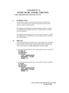
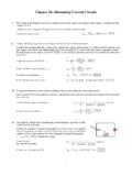
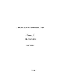
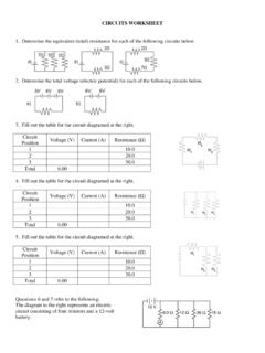
8 Basic formula:2. Remove the divisor by multiplying both sides by R:3-63. Result of step 2: R x I = E4. To get R alone (on one side of the equation) divide both sides by I:5. The basic formula, transposed for R, is:Refer to figure 3-3 where E equals 10 volts and I equals 1 ampere. Solve for R, using the equationjust :E = 10 voltsI = 1 ampereSolution:Figure 3-3. Determining resistance in a basic equation can be used to find the voltage for the circuit shown in figure 3-4. Determining voltage in a basic Ohm s law equation and its various forms may be obtained readily with the aid of figure circle containing E, I, and R is divided into two parts, with E above the line and with I and R belowthe line. To determine the unknown quantity, first cover that quantity with a finger. The position of theuncovered letters in the circle will indicate the mathematical operation to be performed.
9 For example, tofind I, cover I with a finger. The uncovered letters indicate that E is to be divided by R, orTo find the formula for E, cover E with your finger. The result indicates that I is to be multiplied byR, or E = IR. To find the formula for R, cover R. The result indicates that E is to be divided by I, orFigure 3-5. Ohm's law in diagram are cautioned not to rely wholly on the use of this diagram when you transpose the Ohm s lawformulas. The diagram should be used to supplement your knowledge of the algebraic method. Algebra isa basic tool in the solution of electrical problems. Q4. According to Ohm s law, what happens to circuit Current if the applied voltage (a) increases, (b)decreases? Q5. According to Ohm s law, what happens to circuit Current if circuit resistance (a) increases, (b)decreases? Q6. What is the equation used to find circuit resistance if voltage and Current values are known?
10 GRAPHICAL ANALYSIS OF THE BASIC CIRCUITOne of the most valuable methods of analyzing a circuit is by constructing a graph. No other methodprovides a more convenient or more rapid way to observe the characteristics of an electrical first step in constructing a graph is to obtain a table of data. The information in the table can beobtained by taking measurements on the circuit under examination, or can be obtained theoreticallythrough a series of Ohm s law computations. The latter method is used there are three variables (E, I, and R) to be analyzed, there are three distinct graphs that maybe construct any graph of electrical quantities, it is standard practice to vary one quantity in aspecified way and note the changes which occur in a second quantity. The quantity which is intentionallyvaried is called the independent variable and is plotted on the horizontal axis. The horizontal axis isknown as the X-AXIS.