Transcription of 10-Bit, SDTV Video Decoder with Differential …
1 10-Bit, SDTV Video Decoder with Differential InputsData sheet adv7182 Rev. C Document Feedback Information furnished by analog devices is believed to be accurate and reliable. However, no responsibility is assumed by analog devices for its use, nor for any infringements of patents or other rights of third parties that may result from its use. Specifications subject to change without notice. No license is granted by implication or otherwise under any patent or patent rights of analog devices . Trademarks and registered trademarks are the property of their respective owners. One Technology Way, Box 9106, Norwood, MA 02062-9106, : 2013 2014 analog devices , Inc.
2 All rights reserved. Technical Support FEATURES Worldwide NTSC/PAL/SECAM color demodulation support One 10-bit analog -to-digital converter (ADC), 4 oversampling per channel for CVBS, Y/C mode, and YPrPb Four analog Video input channels with on-chip antialiasing filter CVBS (composite), Y/C (S- Video ), and YPrPb (component) Video input support Fully Differential , pseudo Differential , and single-ended CVBS Video input support Up to 4 V common-mode input range solution Excellent common-mode rejection capabilities Five-line adaptive comb filters and CTI/DNR Video enhancement TBC functionality provided by adaptive digital line length tracking (ADLLT), signal processing, and enhanced first in, first out (FIFO) management Integrated automatic gain control (AGC) with adaptive peak white mode Video fast switch capability Adaptive contrast enhancement (ACE) Down dither (8 bits to 6 bits) RoviTM (Macrovision) copy protection detection NTSC/PAL/SECAM autodetection 8-bit ITU-R YCrCb 4:2.
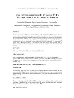
3 2 output and HS, VS, or FIELD Full-featured VBI data slicer with teletext support (WST) Power-down mode and ultralow sleep mode current Two-wire serial MPU interface (I2C compatible) Single V supply possible Automotive qualified models available 40 C to +105 C automotive temperature grade 40 C to +85 C industrial qualified temperature grade 32-lead, 5 mm 5 mm, RoHS-compliant LFCSP APPLICATIONS Automotive infotainment DVRs for Video security Media players FUNCTIONAL BLOCK DIAGRAM Figure 1. AIN1 AIN2 XTALPXTALNAIN3 AIN4 DIFFERENTIALORSINGLE-ENDEDANALOG VIDEOINPUTSAAFILTER 1 AAFILTER 2 AAFILTER 3 AAFILTER 4 DIGITALPROCESSINGBLOCK2D COMBVBI SLICERCOLORDEMODSCLKSDATAALSBRESETPWRDWN 10-BITADCREFERENCEPLLADLLT PROCESSINGCLOCK PROCESSING BLOCKI2C/CONTROLMUX BLOCKFIFOOUTPUT BLOCKADV7182 ADCVS/FIELD/SFLHSLLCINTRQ8-BIT PIXEL DATAP7 TO P0 SHA+ ACEDOWN-DITHER11001-001 adv7182 data sheet TABLE OF CONTENTS Features.
4 1 Applications .. 1 Functional Block Diagram .. 1 Revision History .. 3 General Description .. 4 Overview of the analog Front End .. 4 Overview of the Standard Definition Processor .. 5 Specifications .. 6 Electrical Characteristics .. 6 Video Specifications .. 7 Timing Specifications .. 8 analog Specifications .. 9 Thermal Specifications .. 9 Absolute Maximum Ratings .. 10 ESD Caution .. 10 Pin Configuration and Function Descriptions .. 11 Power Supply Sequencing .. 12 Optimal Power-Up Sequence .. 12 Simplified Power-Up Sequence .. 12 Universal Power Supply .. 12 input Networks .. 13 Single-Ended input Network .. 13 Differential input Network .. 13 Short-to -Battery Protection Section.
5 13 analog Front End .. 14 input Configuration .. 14 analog input Muxing .. 14 Antialiasing Filters .. 16 Global Control Registers .. 17 Power-Saving Modes .. 17 Reset Control .. 17 Global Pin Control .. 17 Global Status Register .. 19 Identification .. 19 Status 1 .. 19 Status 2 .. 19 Status 3 .. 19 Autodetection Result .. 19 Video Processor .. 20 SD Luma Path .. 20 SD Chroma Path .. 20 ACE and Dither Processing Blocks .. 21 Sync Processing .. 21 VBI data Recovery .. 21 General Setup .. 21 Color Controls .. 23 Free-Run Operation .. 25 Clamp Operation .. 26 Luma Filter .. 27 Chroma Filter .. 30 Gain Operation .. 31 Chroma Transient Improvement (CTI).
6 35 Digital Noise Reduction (DNR) and Luma Peaking Filter .. 36 Comb Filters .. 37 IF Filter Compensation .. 39 Adaptive Contrast Enhancement (ACE) .. 39 Dither Function .. 40 AV C o d e I n s ertion and Controls .. 41 Synchronization Output Signals .. 42 Sync Processing .. 49 VBI data Decode .. 49 I2C Readback Registers .. 57 ITU-R Tx Configuration .. 61 MPU Port Description .. 62 Register Access .. 63 Register Programming .. 63 I2C Sequencer .. 63 I2C Register Maps .. 64 PCB Layout Recommendations .. 94 analog Interface Inputs .. 94 Power Supply Decoupling .. 94 VREFN and VREFP .. 94 Digital Outputs (Both data and Clocks) .. 94 Digital Inputs.
7 94 Typical Circuit Connection .. 95 Outline Dimensions .. 96 Ordering Guide .. 96 Automotive Products .. 96 | Page 2 of 96 Rev. CData sheet adv7182 Rev. C | Page 3 of 96 REVISION HISTORY 9/14 Rev. B to Rev. C Changes to input Networks Section .. 13 Changes to analog Interface Inputs Section .. 94 Changes to Figure 50 .. 95 7/14 Rev. A to Rev. B Changes to Features Section .. 1 Moved Revision History .. 3 Changes to General Description Section .. 4 Changes to Table 2 and Table Summary Statement .. 6 Changes to Table 3 Summary Statement .. 7 Change to Table 4 Summary Statement .. 8 Change to Table 5 Summary Statement .. 9 Changes to Table 7 .. 10 Changes to Power Supply Sequencing Section and Figure 5.
8 12 Changes to input Networks Section and Figure 7 .. 13 Change to Antialiasing Filters Section .. 16 Changes to Global Pin Control Section .. 17 Changes to Table 16 .. 19 Changes to Free-Run Operation Section .. 25 Changes to Clamp Operation Section .. 26 Changes to Chroma Filter Section .. 30 Changes to Gain Operation Section .. 32 Changes to Comb Filters Section .. 37 Changed Pixel Port Configuration Section to ITU-R Tx Configuration Section, Moved Polarity LLC Pin Section, Added Figure 45; Renumbered 61 Changes to Table 91 .. 62 Changes to Header Row and Address 0x11, Table 95 .. 68 Change to Header Row, Table 96 .. 83 Changes to Ordering Guide.
9 96 3/13 Rev. 0 to Rev. A Change to Features Section .. 1 Changes to General Description Section .. 4 Changes to Free Run Operation Section and Table 33, Added Luma Ramp Test Pattern Section, VS_COAST_MODE[1:0], Address 0xF9[3:2] Section, and Table 34, Renumbered Sequentially .. 24 Changes to Register 0x14, Table 94 .. 72 Changes to Register 0xF9, Table 94 .. 82 1/13 Revision 0: Initial Version adv7182 data sheet GENERAL DESCRIPTION The adv7182 automatically detects and converts standard analog baseband Video signals compatible with worldwide NTSC, PAL, and SECAM standards into a 4:2:2 component Video data stream. This Video data stream is compatible with the 8-bit ITU-R interface standard.
10 External HS, VS, and FIELD signals can provide timing references for LCD controllers and other Video ASICs. The accurate 10-bit analog -to -digital conversion provides professional quality Video performance for consumer applications with true 8-bit data resolution. The analog Video inputs accept both single-ended, pseudo- Differential , and fully Differential composite Video signals as well as S- Video and YPbPr Video signals, supporting a wide range of consumer and automotive Video sources. The adv7182 along with an external resistor divider provide a common-mode input range of 4 V, enabling the removal of large signal, common-mode transients present on the Video lines.