Transcription of 150mA Low-Noise LDO Regulator - Microchip Technology
1 2017 Microchip Technology 1 MIC5205 Features Ultra-Low noise Output High Output voltage Accuracy Guaranteed 150 mA Output Low Quiescent Current Low dropout voltage Extremely Tight Load and Line Regulation Very Low Temperature Coefficient Current and Thermal Limiting Reverse-Battery Protection Zero Off-Mode Current Logic-Controlled Electronic EnableApplications Cellular Telephones Laptop, Notebook, and Palmtop Computers Battery-Powered Equipment PCMCIA VCC and VPP Regulation/Switching Consumer/Personal Electronics SMPS Post- Regulator and DC/DC Modules High-Efficiency Linear Power SuppliesGeneral DescriptionThe MIC5205 is an efficient linear voltage regulatorwith ultra Low-Noise output, very low dropout voltage (typically 17 mV at light loads and 165 mV at 150 mA),and very low ground current (600 A at 100 mAoutput).
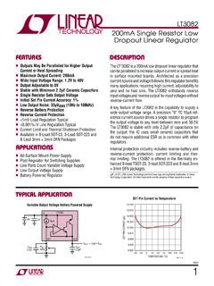
2 The MIC5205 offers better than 1% especially for hand-held, battery-powereddevices, the MIC5205 includes a CMOS or TTLcompatible enable/shutdown control input. When shutdown, power consumption drops nearly to ground current increases only slightly indropout, further prolonging battery MIC5205 features include a reference bypass pinto improve its already excellent Low-Noise performance,reversed-battery protection, current limiting, andovertemperature MIC5205 is available in fixed and adjustable outputvoltage versions in a small SOT-23-5 low- dropout regulators that are stable with ceramicoutput capacitors, see the Cap MIC5245/6/7 TypeMIC52055-Lead SOT-23 (M5)INOUTBYPENLBxxKBxxPartIdentification 1345 INOUTADJENLBAAKBAA134522 GNDGNDPb-FreeMarking150 mA Low-Noise LDO RegulatorMIC5205DS20005785A-page 2 2017 Microchip Technology Application CircuitFunctional Block DiagramsMIC52055-Lead SOT-2315234 COUT= FtantalumCBYPE nableShutdownENVOUTLow- noise Operation:CBYP = 470pF, COUT FBasic Operation:CBYP = not used, COUT 1 (pin 3) may beconnected directlyto IN (pin 1).
3 VININENOUTBYPCBYP(optional) LimitThermal noise Fixed RegulatorINENOUTCBYP(optional) LimitThermal ShutdownCOUTVOUTVINR1R2 MIC5205YM5 ADJVOUT = VREF (1 + R2/R1)Ultra-Low noise Adjustable Regulator 2017 Microchip Technology CHARACTERISTICSA bsolute Maximum Ratings Supply Input voltage (VIN) .. 20V to +20 VEnable Input voltage (VEN) .. 20V to +20 VPower Dissipation (PD) (Note 1) .. Internally LimitedOperating Ratings Supply Input voltage (VIN) .. + to +16 VEnable Input voltage (VEN) ..0V to VIN Notice: Stresses above those listed under Absolute Maximum Ratings may cause permanent damage to the is a stress rating only and functional operation of the device at those or any other conditions above those indicatedin the operational sections of this specification is not intended. Exposure to maximum rating conditions for extendedperiods may affect device reliability.
4 Notice: The device is not guaranteed to function outside its operating 1:The maximum allowable power dissipation at any TA (ambient temperature) is PD(max) = (TJ(max) TA)/ the maximum allowable power dissipation will result in excessive die temperature, and the reg-ulator will go into thermal shutdown. The JA of the MIC5205-xxYM5 (all versions) is 220 C/W mounted ona PC 1-1:ELECTRICAL CHARACTERISTICSE lectrical Characteristics: VIN = VOUT +1V; IL = 100 A; CL = F; VEN ; TJ = +25 C, bold values indicate 40 C < TJ < +125 C, unless voltage AccuracyVO 1 1%Variation from specified VOUT 2 2 Output voltage Temperature Coefficient VO/ T 40 ppm/ CNote 1 Line Regulation VO/VO = VOUT + 1V to 16V Regulation VO/VO = mA to 150 mA, Note 2 voltage , Note 3 VIN VO 1050 mVIL = 100 A 70mV 110150mVIL = 50 mA 230mV 140250 mVIL = 100 mA 300mV 165275 mVIL = 150 mA 350mVQuiescent CurrentIGND 1 AVEN (shutdown) 5 AVEN (shutdown)
5 MIC5205DS20005785A-page 4 2017 Microchip Technology Pin Current, Note 4 IGND 80125 AVEN , IL = 100 A 150 A 350600 AIL = 50 mA 800 A 6001000 AIL = 100 mA 1500 A 13001900 AIL = 150 mA 2500 ARipple RejectionPSRR 75 dBFrequency = 100 Hz, IL = 100 ACurrent LimitILIMIT 320500 mAVOUT = 0 VThermal Regulation VO/ PD %/WNote 5 Output NoiseeNO 260 nV/ HzIL = 50 mA, CL = F, 470 pF from BYP to GNDENABLE InputEnable Input Logic-Low VoltageVIL shutdown Input Logic-High VRegulator enabledEnable Input CurrentIIL 1 AVIL 2 VIL = 25 VIL = 1:Output voltage temperature coefficient is defined as the worst case voltage change divided by the total temperature :Regulation is measured at constant junction temperature using low duty cycle pulse testing. Parts are tested for load regulation in the load range from mA to 150 mA.
6 Changes in output voltage due to heat-ing effects are covered by the thermal regulation : dropout voltage is defined as the input to output differential at which the output voltage drops 2% below its nominal value measured at 1V :Ground pin current is the Regulator quiescent current plus pass transistor base current. The total current drawn from the supply is the sum of the load current plus the ground pin :Thermal regulation is defined as the change in output voltage at a time t after a change in power dissipa-tion is applied, excluding load or line regulation effects. Specifications are for a 150 mA load pulse at VIN = 16V for t = 10 1-1:ELECTRICAL CHARACTERISTICS (CONTINUED)Electrical Characteristics: VIN = VOUT +1V; IL = 100 A; CL = F; VEN ; TJ = +25 C, bold values indicate 40 C < TJ < +125 C, unless 2017 Microchip Technology 5 MIC5205 TEMPERATURE SPECIFICATIONS (Note 1) RangesJunction Operating Temperature RangeTJ 40 +125 C Storage Temperature RangeTS 65 +150 C Lead Temperature +260 CSoldering, 5sPackage Thermal ResistancesThermal Resistance SOT-23-5 JA 220 C/WNote 2 JC 130 C/W Note 1:The maximum allowable power dissipation is a function of ambient temperature, the maximum allowable junction temperature and the thermal resistance from junction to air ( , TA, TJ, JA).
7 Exceeding the maximum allowable power dissipation will cause the device operating junction temperature to exceed the maximum +125 C rating. Sustained junction temperatures above +125 C can impact the device :The maximum allowable power dissipation at any TA (ambient temperature) is PD(max) = (TJ(max) TA)/ JA. Exceeding the maximum allowable power dissipation will result in excessive die temperature, and the reg-ulator will go into thermal shutdown. The JA of the MIC5205-xxYM5 (all versions) is 220 C/W mounted on a PC 6 2017 Microchip Technology PERFORMANCE CURVESFIGURE 2-1:Power Supply Rejection Ratio. FIGURE 2-2:Power Supply Rejection 2-3:Power Supply Ripple Rejection vs. voltage 2-4:Power Supply Rejection 2-5:Power Supply Rejection 2-6:Power Supply Ripple Rejection vs. voltage :The graphs and tables provided following this note are a statistical summary based on a limited number ofsamples and are provided for informational purposes only.
8 The performance characteristics listed hereinare not tested or guaranteed. In some graphs or tables, the data presented may be outside the specifiedoperating range ( , outside specified power supply range) and therefore outside the warranted +1 1E+2 1E+3 1E+4 1E+5 1E+6 1E+7)Bd( RRSPFREQUENCY (Hz)IOUT = 100 ACOUT = 1 FVIN = 6 VVOUT = 5V101001k10k100k1M10M-100-80-60-40-2001E +1 1E+2 1E+3 1E+4 1E+5 1E+6 1E+7)Bd( RRSPFREQUENCY (Hz)IOUT = 100 ACOUT = FCBYP = FVIN = 6 VVOUT = )Bd( NOITCEJER ELPPIRVOLTAGE DROP (V)IOUT = 100mA10mA1mACOUT = 1 F-100-80-60-40-2001E+1 1E+2 1E+3 1E+4 1E+5 1E+6 1E+7)Bd( RRSPFREQUENCY (Hz)IOUT = 1mACOUT = 1 FVIN = 6 VVOUT = 5V101001k10k100k1M10M-100-80-60-40-2001E +1 1E+2 1E+3 1E+4 1E+5 1E+6 1E+7)Bd( RRSPFREQUENCY (Hz)IOUT = 1mACOUT = FCBYP = FVIN = 6 VVOUT = )Bd( NOITCEJER ELPPIRVOLTAGE DROP (V)
9 IOUT = 100mA10mA1mACOUT = FCBYP = F 2017 Microchip Technology 7 MIC5205 FIGURE 2-7:Power Supply Rejection 2-8:Power Supply Rejection 2-9:Turn-On Time vs. Bypass 2-10:Power Supply Rejection 2-11:Power Supply Rejection 2-12: dropout voltage vs. Output +1 1E+2 1E+3 1E+4 1E+5 1E+6 1E+7)Bd( RRSPFREQUENCY (Hz)IOUT = 10mACOUT = 1 FVIN = 6 VVOUT = 5V101001k10k100k1M10M-100-80-60-40-2001E +1 1E+2 1E+3 1E+4 1E+5 1E+6 1E+7)Bd( RRSPFREQUENCY (Hz)IOUT = 10mACOUT = FCBYP = FVIN = 6 VVOUT = 5V101001k10k100k1M10M1010010001000010100 100010000( EMIT )sCAPACITANCE (pF)-100-80-60-40-2001E+1 1E+2 1E+3 1E+4 1E+5 1E+6 1E+7)Bd( RRSPFREQUENCY (Hz)IOUT = 100mACOUT = 1 FVIN = 6 VVOUT = 5V101001k10k100k1M10M-100-80-60-40-2001E +1 1E+2 1E+3 1E+4 1E+5 1E+6 1E+7)Bd( RRSPFREQUENCY (Hz)IOUT = 100mACOUT = FCBYP = FVIN = 6 VVOUT = 5V101001k10k100k1M10M0408012016020024028 032004080120160)Vm( EGATLOV TUOPORDOUTPUT CURRENT (mA)+125 C+25 C 40 CMIC5205DS20005785A-page 8 2017 Microchip Technology 2-13: noise 2-14: noise 2-15: noise 2-16: noise 2-17.
10 noise 2-18: noise +1 1E+2 1E+3 1E+4 1E+5 1E+6 1E+7( ESION /V )zHFREQUENCY (Hz)101001k10k 100k 1M 10M1mACOUT = 1 FCBYP = 10nF10mA, COUT = 1 FVOUT = +1 1E+2 1E+3 1E+4 1E+5 1E+6 1E+7( ESION /V)zHFREQUENCY (Hz)10mA1mA100mA101001k10k 100k1M10 MVOUT = 5 VCOUT = 10 Felectrolytic +1 1E+2 1E+3 1E+4 1E+5 1E+6 1E+7( ESION /V )zHFREQUENCY (Hz)10mA1mA100mA101001k10k 100k1M10 MVOUT = 5 VCOUT = 22 FtantalumCBYP = +1 1E+2 1E+3 1E+4 1E+5 1E+6 1E+7( ESION /V )zHFREQUENCY (Hz)10mA1mA100mA101001k10k 100k1M10 MVOUT = 5 VCOUT = 10 FelectrolyticCBYP = +1 1E+2 1E+3 1E+4 1E+5 1E+6 1E+7( ESION /V )zHFREQUENCY (Hz)10mA1mA100mA101001k10k 100k1M10 MVOUT = 5 VCOUT = 10 FelectrolyticCBYP = +1 1E+2 1E+3 1E+4 1E+5 1E+6 1E+7( ESION /V )zHFREQUENCY (Hz)10mA1mA100mA101k10010k100k1M10 MVOUT = 5 VCOUT = 10 FelectrolyticCBYP = 10nF 2017 Microchip Technology DESCRIPTIONSThe descriptions of the pins are listed in Table 3-1:PIN FUNCTION TABLEPin NumberFixed VersionPin NumberAdj.