Transcription of 20-Bit, 1.8 MSPS/1 MSPS/500 kSPS, Easy Drive, Differential ...
1 20-Bit, MSPS/1 MSPS/500 kSPS, Easy Drive, Differential SAR ADCs Data Sheet AD4020/AD4021/AD4022 Rev. C Document Feedback Information furnished by Analog Devices is believed to be accurate and reliable. However, no responsibility is assumed by Analog Devices for its use, nor for any infringements of patents or other rights of third parties that may result from its use. Specifications subject to change without notice. No license is granted by implication or otherwise under any patent or patent rights of Analog Devices. Trademarks and registered trademarks are the property of their respective owners One Technology Way, Box 9106, Norwood, MA 02062-9106, Tel: 2017 2021 Analog Devices, Inc. All rights reserved. Technical Support FEATURES Easy Drive Greatly reduced input kickback Input current reduced to A/MSPS Enhanced acquisition phase, 77% of cycle time at 1 MSPS First conversion accurate, no latency or pipeline delay Input span compression for single-supply operation Fast conversion allows low SPI clock rates Input overvoltage clamp protection sinks up to 50 mA SPI-/QSPI-/MICROWIRE-/DSP-compatible serial interface High performance Differential analog input range: VREF, VREF from V to V Throughput: MSPS/1 MSPS/500 kSPS options INL: ppm maximum Guaranteed 20-bit, no missing codes SNR: dB at fIN = 1 kHz, VREF = 5 V THD: 123 dB at fIN = 1 kHz, 100 dB at fIN = 100 kHz SINAD.
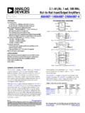
2 89 dB at fIN = 900 kHz (see Figure 17) Oversampled dynamic range 104 dB for OSR = 2 131 dB for OSR = 1024 Low power Single V supply operation with V to V logic interface mW at 500 kSPS (VDD only) 83 W at 10 kSPS, 15 mW at MSPS (total power) 10-lead packages: 3 mm 3 mm lfcsp , 3 mm mm msop Pin compatible with AD4003/AD4007/AD4011 family Guaranteed operation: 40 C to +125 C APPLICATIONS Automated t est equipment Machine automation Medical equipment Battery-powered equipment Precision data acquisition systems Instrumentation and control systems FUNCTIONAL BLOCK DIAGRAM GNDIN+IN SDISCKSDOCNVAD4020/AD4021/AD402220-BITSA R ADCSERIALINTERFACEVIOREFVDDVREF0 VREF0 VREF/2 TO TO 5V3-WIRE OR4-WIRE SPIINTERFACE(DAISYCHAIN, CS)15369-001 Figure 1. GENERAL DESCRIPTION The AD4020/AD4021/AD4022 are high accuracy, high speed, low power, 20-bit, Easy Drive, precision successive approximation register (SAR) analog-to -digital converters (ADCs) that operate from a single power supply, VDD.
3 The reference voltage, VREF, is applied externally and can be set independent of the supply voltage. The AD4020/AD4021/AD4022 power scales linearly with throughput. Easy Drive features reduce both signal chain complexity and power consumption while enabling higher channel density. The reduced input current, particularly in high-Z mode, coupled with a long signal acquisition phase, eliminates the need for a dedicated ADC driver. Easy Drive broadens the range of companion circuitry that is capable of driving these ADCs (see Figure 2). Input span compression eliminates the need to provide a negative supply to the ADC driver amplifier while preserving access to the full ADC code range. The input overvoltage clamp protects the ADC inputs against overvoltage events, minimizing disturbances on the reference pin, and eliminating the need for external protection diodes.
4 Fast device throughput up to MSPS allows users to accurately capture high frequency signals and to implement oversampling techniques to alleviate the challenges associated with antialias filter designs. Decreased serial peripheral interface (SPI) clock rate requirements reduce digital input/output power consumption, broadens digital host options, and simplifies the task of sending data across digital isolation. The SPI-compatible serial user interface is compatible with V, V, 3 V, and 5 V logic by using the separate VIO logic supply. 18 15 9 361215 12 6039 5 3 1531 INPUT CURRENT ( A)INPUT Differential VOLTAGE (V)15369-14725 C HIGH-Z ENABLED, C HIGH-Z DISABLED, 2. Input Current vs. Input Differential Voltage AD4020/AD4021/AD4022 Data Sheet Rev. C | Page 2 of 40 TABLE OF CONTENTS Features .. 1 Applications .. 1 Functional Block Diagram.
5 1 General Description .. 1 Revision History .. 2 Specifications .. 4 Timing Specifications .. 7 Absolute Maximum Ratings .. 9 Thermal Resistance .. 9 ESD Caution .. 9 Pin Configurations and Function Descriptions .. 10 Typical Performance Characteristics .. 11 Terminology .. 17 Theory of Operation .. 18 Circuit Information .. 18 Converter Operation .. 19 Transfer 19 Applications Information .. 20 Typical Application Diagrams .. 20 Analog Inputs .. 21 Driver Amplifier Choice .. 22 Ease of Drive Features .. 24 Voltage Reference Input .. 25 Power Supply .. 25 Digital Interface .. 26 Register Read/Write 28 Status Bits .. 30 CS Mode, 3-Wi r e Tu r b o M o d e .. 31 CS Mode, 3-Wire Without Busy Indicator .. 32 CS Mode, 3-Wire with Busy Indicator .. 33 CS Mode, 4-Wi r e Tu r b o M o d e .. 34 CS Mode, 4-Wire Without Busy Indicator.
6 35 CS Mode, 4-Wire with Busy Indicator .. 36 Daisy-Chain Mode .. 37 Layout 38 Evaluating the AD4020/AD4021/AD4022 Performance .. 38 Outline Dimensions .. 39 Ordering Guide .. 40 REVISION HISTORY 2/2021 Rev. B to Rev. C Changes to Features Section and Applications Section .. 1 Changes to Specifications Section .. 4 Changed Voltage Range (VREF) Parameter, Table 1 to VREF Voltage Range Parameter, Table 5 Changes to VREF Voltage Range Parameter, Table 1 .. 5 Changed CNV or SDI Low to SDO D17 MSB Valid Delay (CS Mode) Parameter, Table 2 to CNV or SDI Low to SDO D19 MSB Valid Delay (CS Mode) Parameter, Table 2 .. 7 Changes CNV Low to SDO D17 MSB Valid Delay Parameter, Table 3 to CNV Low to SDO D19 MSB Valid Delay Parameter, Ta b l e 3 .. 8 Changes to Figure 35 Caption .. 16 Changes to Table 8 .. 18 Changes to Input Overvoltage Clamp Circuit Section.
7 21 Changes to Driver Amplifier Choice Section and Ta b l e 1 0 .. 22 Changes to High-Z Mode Section .. 24 Changes to Figure 47, Figure 38, and Power Supply Section .. 25 Changes to Serial Clock Frequency Requirements Section .. 26 Added Note 1 to Table 13 .. 27 Changes to Register Read/Write Functionality Section .. 28 Changes to Status Bits Section .. 30 Changes to CS Mode, 3-Wire Turbo Mode Section .. 31 Changes to Figure 58 .. 33 Changes to CS Mode, 4-Wire Without Busy Indicator Mode Section .. 35 Changes to CS Mode, 4-Wire With Busy Indicator Mode Section and Figure 36 Changes to Daisy-Chain Mode Section .. 37 Updated Outline Dimensions .. 42 Changes to Ordering Guide .. 43 11/2019 R e v. A to R e v. B Added AD4021 and AD4022 .. Universal Added Figure 2; Renumbered Sequentially .. 1 Changes to Features Section and General Description Section.
8 1 Changes to Specifications Section and Table 1 .. 4 Changes to Timing Specifications Section and Ta b l e 2 .. 7 Deleted Figure 3; Renumbered Sequentially .. 8 Changes to Table 3 .. 8 Added Endnote 2, Table 5 .. 9 Changes to Absolute Maximum Ratings Section and Thermal Resistance Section .. 9 Changes to Figure 4 and Table 7 .. 10 Data Sheet AD4020/AD4021/AD4022 Rev. C | Page 3 of 40 Changes to Typical Performance Characteristics Section .. 11 Added Figure 30 and Figure 31 .. 15 Changes to Terminology Section .. 17 Changes to Circuit Information Section and Table 8 .. 18 Changes to Converter Operation Section and Endnote 1 and Endnote 2, Table 9 .. 19 Changes to Typical Application Diagrams Section .. 20 Changes to Input Overvoltage Clamp Circuit Section .. 21 Changes to Figure 44, Single to Differential Driver Section, and High Frequency Input Signals Section.
9 23 Changes to High-Z Mode Section, Figure 47 Caption, and Figure 48 Caption .. 24 Deleted Table 12, Ta b l e 1 3, and Table 14; Renumbered Sequentially .. 25 Changes to Voltage Reference Input Section, Power Supply Section, and Digital Interface Section .. 25 Added Configuration Register Details Section .. 25 Added Serial Clock Frequency Requirements Section, Table 12, and Table 13; Renumbered Sequentially .. 26 Changes to Register Read/Write Functionality Section, Table 14, and Figure 49 .. 27 Changes to Figure 50 .. 28 Changed Status Word Section to Status Bits Section .. 29 Changes to Status Bits Section and Table 15 .. 29 Changes to CS Mode, 3-Wire Turbo Mode Section, Figure 54 Caption, and Figure 54 Caption .. 30 Changes to CS Mode, 3-Wire Without the Busy Indicator Section, Figure 55 Caption, and Figure 56 Caption .. 31 Changes to CS Mode, 3-Wire with the Busy Indicator Section, Figure 57 Caption, and Figure 58 Caption.
10 32 Changes to CS Mode, 4-Wire Turbo Mode Section and Figure 60 Caption .. 33 Changes to CS Mode, 4-Wire Without the Busy Indicator Section and Figure 62 Caption .. 34 Changes to CS Mode, 4-Wire with the Busy Indicator Section and Figure 64 Caption .. 35 Changes to Daisy-Chain Mode Section and Figure 66 Caption .. 36 Changes to Layout Guidelines Section and Evaluating the AD4020/AD4021/AD4022 Performance Section .. 37 Changes to Ordering Guide .. 39 7/2017 R e v. 0 to R e v. A Change to Integral Nonlinearity Error (INL) Parameter, Ta b l e 1 .. 3 7/ 2017 Revision 0: Initial Ve r s i on AD4020/AD4021/AD4022 Data Sheet Rev. C | Page 4 of 40 SPECIFICATIONS VDD = V to V, VIO = V to V, REF = VREF = 5 V, all specifications TMIN to TMAX, high-Z mode disabled, span compression disabled, turbo mode enabled, and sampling frequency (fS) = MSPS for the AD4020, fS = 1 MSPS for the AD4021, and fS = 500 kSPS for the AD4022, unless otherwise noted.