Transcription of 24AA256/24LC256/24FC256 Data Sheet - Microchip …
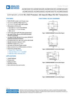
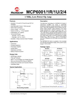
1 1998-2019 Microchip Technology 124AA256/ 24lc256 / 24fc256 Device Selection TableFeatures Single Supply with Operation Down to for 24aa256 and 24fc256 Devices, for 24lc256 Devices Low-Power CMOS Technology:- Write current: 3 mA, maximum- Standby current: 1 A maximum (I-temp.) Two-Wire Serial Interface, I2C Compatible Cascadable up to Eight Devices Schmitt Trigger Inputs for Noise Suppression Output Slope Control to Eliminate Ground Bounce 100 kHz, 400 kHz and 1 MHz Compatibility Page Write Time: 5 ms, maximum Self-Timed Erase/Write Cycle 64-Byte Page Write Buffer Hardware Write-Protect ESD Protection >4000V More than One Million Erase/Write Cycles Data Retention >200 years Factory Programming Available RoHS Compliant Temperature Ranges.
2 Automotive AEC-Q100 QualifiedPackages 8-Lead DFN, 8-Lead MSOP, 8-Lead PDIP, 8-Lead SOIC, 8-Lead SOIJ, 8-Lead TDFN, 8-Lead TSSOP and 8-Ball CSPD escriptionThe Microchip Technology Inc. 24XX256(1) is a 32K x 8(256 Kbit) Serial Electrically Erasable PROM, capableof operation across a broad voltage range ( ). It has been developed for advanced, low-powerapplications such as personal communications or dataacquisition. This device also has a page write capabilityof up to 64 bytes of data. This device is capable of bothrandom and sequential reads up to the 256K address lines allow up to eight devices onthe same bus, for up to 2 Mbit address TypesPart NumberVCC RangeMax.
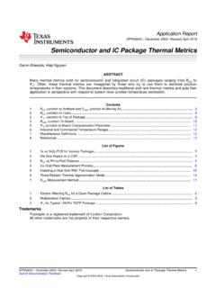
3 Clock FrequencyTemp. RangesAvailable kHz(1)I, EMF, MS, P, SN, SM, MNY, ST, kHzI, EMF, MS, P, SN, SM, MNY, MHz(2)IMF, MS, P, SN, SM, MNY, STNote 1:100 kHz for VCC< :400 kHz for VCC< Industrial (I):-40 C to +85 C- Extended (E): -40 C to +125 CNote 1:24XX256 is used in this document as ageneric part number for the 24AA256/24LC256/24FC256 CSP 12345678 VCCA1 A0 WPA2 SDA SCL VSS123487658-Lead SOIC/SOIJ/TSSOP8-Lead DFN/TDFNVSSWPSCLSDAVCC(Top View)(Top View)123487658-Lead PDIP/MSOP(Top View)WPSCLSDAVCC12348765 WPSCLSDAVCC12348765A0A1A2 VSSA0A1A2 VSSA0A1A224XX25624XX25624XX256(Top View)Note 1.
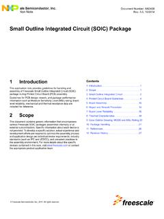
4 Pins A0 and A1 are no connects for the MSOP package only.(1)256K I2C Serial EEPROM24AA256/ 24lc256 /24FC256DS20001203W -page 2 1998-2019 Microchip Technology DiagramHV GeneratorEEPROM ArrayPage LatchesYDECXDECS ense ControlMemoryControlLogicI/OControlLogic I/OA0 A1 A2 SDASCLVCCVSSWP 1998-2019 Microchip Technology 324AA256/ 24lc256 CHARACTERISTICSA bsolute Maximum Ratings( ) inputs and outputs to VCC + temperature .. -65 C to +150 CAmbient temperature with power -40 C to +125 CESD protection on all pins 4kV NOTICE: Stresses above those listed under Absolute Maximum Ratings may cause permanent damage to thedevice.
5 This is a stress rating only and functional operation of the device at these or any other conditions above thoseindicated in the operational listings of this specification is not implied. Exposure to Absolute Maximum Ratingconditions for extended periods may affect device 1-1:DC CHARACTERISTICSDC CHARACTERISTICSE lectrical Characteristics:Industrial (I):VCC = + to = -40 C to +85 CExtended (E):VCC = + to = -40 C to +125 Input VCC VD2 VILLow-Level Input Voltage VCCVVVCC < of Schmitt Trigger Inputs (SDA, SCL pins) VCC VVCC (Note)D4 VOLLow-Level Output Voltage = mA @ VCC = = mA @ VCC = Leakage Current 1 AVIN = VSS or VCC, WP = VSSVIN = VSS or VCC, WP = VCCD6 ILOO utput Leakage Current 1 AVOUT = VSS or VCCD7 CIN, COUTPin Capacitance (all inputs/outputs) 10pFVCC = (Note)TA = 25 C, FCLK = 1 MHzD8 ICC Read Operating Current 400 AVCC = , SCL = 400 kHzICC Write 3mAVCC = Current 1 ASDA = SCL = VCC= , A1, A2, WP = VSS, I-Temp.
6 ASDA = SCL = VCC= , A1, A2, WP = VSS, I-Temp. 5 ASDA = SCL = VCC= , A1, A2, WP = VSS, :This parameter is periodically sampled and not 100% 4 1998-2019 Microchip Technology 1-2:AC CHARACTERISTICSAC CHARACTERISTICSE lectrical Characteristics:Industrial (I):VCC = + to = -40 C to +85 CExtended (E):VCC = + to = -40 C to +125 Frequency VCC VCC VCC ( 24fc256 ) VCC ( 24fc256 )2 THIGHC lock High Time4000 VCC VCC VCC ( 24fc256 )500 VCC ( 24fc256 )3 TLOWC lock Low Time4700 VCC VCC VCC ( 24fc256 )500 VCC ( 24fc256 )4 TRSDA and SCL Rise Time VCC (Note 1) VCC (Note 1) VCC ( 24fc256 ) (Note 1)5 TFSDA and SCL Fall Time 300nsAll except 24fc256 (Note 1) VCC ( 24fc256 ) (Note 1)6 THD.
7 STAS tart Condition Hold Time4000 VCC VCC VCC ( 24fc256 )250 VCC ( 24fc256 )7 TSU:STAS tart Condition Setup Time4700 VCC VCC VCC ( 24fc256 )250 VCC ( 24fc256 )8 THD:DATData Input Hold Time0 nsNote 29 TSU:DATData Input Setup Time250 VCC VCC VCC ( 24fc256 )10 TSU:STOStop Condition Setup Time4000 VCC VCC VCC ( 24fc256 )250 VCC ( 24fc256 )Note 1:Not 100% tested. CB = total capacitance of one bus line in :As a transmitter, the device must provide an internal minimum delay time to bridge the undefined region (minimum 300 ns) of the falling edge of SCL to avoid unintended generation of Start or Stop :The combined TSP and VHYS specifications are due to new Schmitt Trigger inputs, which provide improved noise spike suppression.
8 This eliminates the need for a TI specification for standard :This parameter is not tested but ensured by characterization. For endurance estimates in a specific application, please consult the Total Endurance Model, which can be obtained from Microchip s website at 1998-2019 Microchip Technology 524AA256/ 24lc256 /24FC25611 TSU:WPWP Setup Time4000 VCC VCC VCC ( 24fc256 )12 THD:WPWP Hold Time4700 VCC VCC VCC ( 24fc256 )13 TAAO utput Valid from Clock V VCC (Note 2) V VCC (Note 2) VCC ( 24fc256 ) (Note 2) V VCC ( 24fc256 ) (Note 2)14 TBUFBus Free Time.
9 The time the bus must be free before a new transmission can start4700 VCC VCC VCC ( 24fc256 )500 VCC ( 24fc256 )15 TOFO utput fall time from VIHminimum to VIL maximumCB 100 pF 10 + except 24fc256 (Note 1)250nsAll except 24fc256 (Note 1)16 TSPI nput Filter Spike Suppression(SDA and SCL pins) 50nsAll except 24fc256 (Notes 1 and3)17 TWCW rite Cycle Time (byte or page) 5ms18 Endurance1,000,000 cycles 25 C, , Page mode (Note 4)TABLE 1-2:AC CHARACTERISTICSAC CHARACTERISTICS (Continued)Electrical Characteristics:Industrial (I):VCC = + to = -40 C to +85 CExtended (E):VCC = + to = -40 C to +125 1:Not 100% tested.
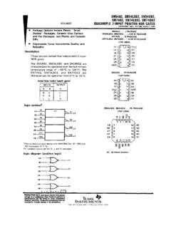
10 CB = total capacitance of one bus line in :As a transmitter, the device must provide an internal minimum delay time to bridge the undefined region (minimum 300 ns) of the falling edge of SCL to avoid unintended generation of Start or Stop :The combined TSP and VHYS specifications are due to new Schmitt Trigger inputs, which provide improved noise spike suppression. This eliminates the need for a TI specification for standard :This parameter is not tested but ensured by characterization. For endurance estimates in a specific application, please consult the Total Endurance Model, which can be obtained from Microchip s website at 6 1998-2019 Microchip Technology 1-1:BUS TIMING DATA(unprotected)(protected)SCLSDAINSDAO UTWP57616328913D3410111214 1998-2019 Microchip Technology 724AA256/ 24lc256 DESCRIPTIONSThe descriptions of the pins are listed in Table 2-1:PIN FUNCTION , A1, A2 Chip Address InputsThe A0, A1 and A2 inputs are used by the 24XX256 formultiple device operations.