Transcription of 4-Channel, ±10 V Input Range, High Throughput, 24-Bit ...
1 4- channel , 10 V Input Range, high throughput , 24-Bit sigma - delta ADCData Sheet AD7734 Rev. B Document Feedback Information furnished by analog devices is believed to be accurate and reliable. However, no responsibility is assumed by analog devices for its use, nor for any infringements of patents or other rights of third parties that may result from its use. Specifications subject to change without notice. No license is granted by implication or otherwise under any patent or patent rights of analog devices . Trademarks and registered trademarks are the property of their respective owners. One Technology Way, Box 9106, Norwood, MA 02062-9106, : 2003 2015 analog devices , Inc.
2 All rights reserved. Technical Support FEATURES high resolution analog -to-digital converter (ADC) 24 bits no missing codes nonlinearity Optimized for fast channel switching 18-bit p-p resolution (21 bits effective) at 500 Hz 16-bit p-p resolution (19 bits effective) at 2 kHz 14-bit p-p resolution (18 bits effective) at 15 kHz On-chip per channel system calibration 4 single-ended analog inputs I n p u t ra n g e s + 5 V, 5 V, + 1 0 V, 1 0 V Overvoltage tolerant Up to V not affecting adjacent channel Up to 50 V absolute maximum 3-wire serial interface SPI, QSPI , MICROWIRE, and DSP compatible Schmitt trigger on logic inputs Single-supply operation 5 V analog supply 3 V or 5 V digital supply Package.
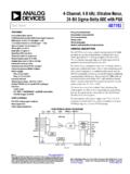
3 28-lead TSSOP APPLICATIONS PLCs/DCS Multiplexing applications Process control Industrial instrumentation FUNCTIONAL BLOCK DIAGRAM P0 SYNC/P1 AIN0 AIN2 AIN1 AIN3 BIASHIBIASLOSCLKDINDOUTCSRESETRDYDGNDMCL KINMCLKOUTAGND AVDDDVDDBUFFERREFERENCEDETECTREFIN( )REFIN(+)AD773424-BIT - ADCSERIALINTERFACECONTROLLOGICCLOCKGENER ATORCALIBRATIONCIRCUITRYI/O PORTMUX03071-001 Figure 1. GENERAL DESCRIPTION The AD7734 is a high precision, high throughput analog front end. True 16-bit p-p resolution is achievable with a total conversion time of 500 s (2 kHz channel switching), making it ideally suitable for high resolution multiplexing applications.
4 The device can be configured via a simple digital interface, which allows users to balance the noise performance against data throughput up to kHz. The analog front end features four single-ended Input channels with unipolar or true bipolar Input ranges to 10 V while operating from a single +5 V analog supply. The device has an overrange and underrange detection capability and accepts an analog Input overvoltage to V without degrading the performance of the adjacent channels. The differential reference Input features No-Reference detect capability. The ADC also supports per channel system calibra-tion options. The digital serial interface can be configured for 3-wire operation and is compatible with microcontrollers and digital signal processors.
5 All interface inputs are Schmitt triggered. The device is specified for operation over the extended industrial temperature range of 40 C to +105 C. Other devices in the AD7734 family are the AD7732 and the AD7738. The AD7732 is similar to the AD7734, but its analog front end features two fully differential Input channels. The AD7738 analog front end is configurable for four fully differential or eight single-ended Input channels, features V to V bipolar/unipolar Input ranges , and accepts a common-mode Input voltage from 200 mV to AVDD 300 mV. The AD7738 multiplexer output is pinned out externally, allowing the user to implement programmable gain or signal conditioning before being applied to the ADC.
6 AD7734 Data Sheet Rev. B | Page 2 of 32 TABLE OF CONTENTS Features .. 1 Applications .. 1 Functional Block Diagram .. 1 General Description .. 1 Revision History .. 2 Specifications .. 3 Timing Specifications .. 6 Absolute Maximum Ratings .. 8 ESD Caution .. 8 Typical Performance Characteristics .. 9 Output Noise and Resolution Specification .. 10 Chopping Enabled .. 10 Chopping Disabled .. 11 Pin Configuration and Function Descriptions .. 12 Register Description .. 14 Register Access .. 15 Communications Register .. 15 I/O Port Register .. 16 Revision Register .. 16 Test Register .. 16 ADC Status Register .. 16 Checksum Register.
7 17 ADC Zero-Scale Calibration Register .. 17 ADC Full-Scale Register .. 17 channel Data 17 channel Zero-Scale Calibration Registers .. 18 channel Full-Scale Calibration Registers .. 18 channel Status Registers .. 18 channel Setup Registers .. 19 channel Conversion Time Registers .. 19 Mode Register .. 20 Digital Interface Description .. 22 Hardware .. 22 Reset .. 23 Access the AD7734 Registers .. 23 Single Conversion and Reading Data .. 23 Dump Mode .. 24 Continuous Conversion Mode .. 24 Continuous Read (Continuous Conversion) Mode .. 25 Circuit 26 analog Front End .. 26 analog Input s Extended Voltage Range .. 27 Chopping.
8 27 Multiplexer, Conversion, and Data Output Timing .. 28 - ADC .. 28 Frequency Response .. 29 Voltage Reference Inputs .. 29 Reference Detect .. 29 I/O Port .. 30 Calibration .. 30 ADC Zero-Scale Self-Calibration .. 30 Per channel System Calibration .. 30 Outline Dimensions .. 32 Ordering Guide .. 32 REVISION HISTORY 9/15 Rev. A to Rev. B Change to Figure 14 .. 22 Changes to Figure 28 .. 29 Changes to Ordering Guide .. 32 7/12 Rev. 0 to Rev. A Changes to ADC Performance Chop Enabled Parameter .. 3 Changes to Figure 22 .. 25 2/03 Revision 0: Initial Version Data Sheet AD7734 Rev. B | Page 3 of 32 SPECIFICATIONS 40 C to +105 C; AVDD = 5 V 5%; DVDD = V to V, or 5 V 5%; BIAS0 to BIAS3, BIASHI, REFIN(+) = V; BIASLO, REFIN( ) = AGND; AIN Range = 10 V; fMCLKIN = MHz; unless otherwise noted.
9 Table 1. Parameter Min Typ Max Unit Test Conditions/Comments ADC PERFORMANCE CHOPPING ENABLED Conversion Time Rate 372 12190 Hz Configure via Conv. Time Register No Missing Codes1, 2 24 Bits FW 6 (Conversion Time 165 s) Output Noise See Table 4 Resolution See Table 5 and Table 6 Integral Nonlinearity (INL)1, 2 % of FSR fMCLKIN = MHz Integral Nonlinearity (INL)2 % of FSR fMCLKIN = MHz Offset Error (Unipolar, Bipolar)3 13 mV Before Calibration Offset Drift vs. Temperature1 V/ C Gain Error3 % Before Calibration Gain Drift vs. Temperature1 ppm of FS/ C Positive Full-Scale Error3 % of FSR Before Calibration Positive Full-Scale Drift vs.
10 3 ppm of FS/ C Bipolar Negative Full-Scale Error4 % of FSR After Calibration Power Supply Sensitivity 4 10 LSB16 At DC, AIN = 7 V, AVDD = 5 V 5% channel -to- channel Isolation 110 dB At DC, Maximum V AIN Voltage ADC PERFORMANCE CHOPPING DISABLED Conversion Time Rate 737 15437 Hz Configure via Conv. Time Register No Missing Codes1, 2 24 Bits FW 8 (Conversion Time 117 s) Output Noise See Table 7 Resolution See Table 8 and Table 9 Integral Nonlinearity (INL)2 % of FSR Offset Error (Unipolar, Bipolar)5 15 mV Before Calibration Offset Drift vs. Temperature 25 V/ C Gain Error3 % Before Calibration Gain Drift vs.