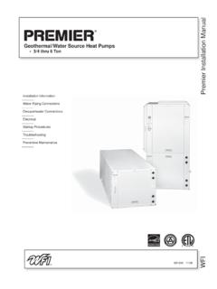
Transcription of 5 Series 500A11 Installation Manual - WaterFurnace
1 IM2500AN 11/17 Installation InformationWater Piping ConnectionsHot Water Generator ConnectionsElectricalStartup ProceduresTroubleshootingPreventive Maintenance5 Series 500A11 Installation ManualGeothermal Heat Pump R-410A Refrigerant 1, , 2, , 3, , 4, 5, 6 Ton Single Speed 2, 3, 4, 5, 6 Ton Dual Capacity500A11ormationonnectionserator Connectionsuresgntenance5 Series 500A11 Installation MANUALT able of ContentsModel Nomenclature .. 4 General Installation Information .. 5 Closed Loop Ground Source Systems.
2 10 Open Loop Ground Water Systems .. 11 Hot Water Generator Connections .. 12 Electrical Connections.. 14 Electronic Thermostat Installation .. 16 Auxiliary Heat Ratings .. 17 Auxiliary Heat Electrical Data .. 17 Electrical Data .. 18 Blower Performance Data .. 20 Dimensional Data .. 25 Physical Data.. 29 The Aurora Control System .. 31 Reference Calculations and Legend .. 41 Wiring Schematics .. 42 Unit Startup.. 55 Operating Parameters .. 57 Pressure Drop .. 59 Compressor and Thermistor Resistance ..60 Refrigerant Circuit Guideline.
3 60 Heat of Extraction/Rejection .. 61 Troubleshooting .. 62 Preventive Maintenance .. 66 Replacement Procedures .. 66 Service Parts List .. 6745 Series 500A11 Installation MANUALM odel NomenclatureN1234-6789 Model Type N 5 Series Water-to-AirCompressor Type D Dual-Sta ge S Single StageC abi ne t Co n figu r ati on V Vertical H - HorizontalUnit Capacity (MBTUH) 012, 018, 022, 026, 030 036, 038, 042, 048, 049 060, 064, 070, 072 Vintage * Internal Factory Use OnlyVoltage 1 208-230/60/1H ot W ate r Gen er ati on 0 No H ot W ate r G ene ra ti on 1 H ot W ate r Gen er ati on w it h Fac tory Inst all ed P umpBlower Options 0 P SC (Sin gle St age O nl y) 1 Variable Speed E CM 2 High Static Variable Spe ed ECM (036-049 Only) 3 High St ati c PSC (02 2, 03 0, 03 6, 04 2, 04 8)
4 4 5-Speed ECM (02 2-07 2)IntelliStart & Ai r Coi l Opti on* N No IntelliStart, Uncoated Coil A IntelliStart, Uncoated Coil B No IntelliStart, AlumiSeal C IntelliStart, AlumiSealControl Option A AuroraTM Base Control (ABC) B Aurora Advanced Control (ABC & AX B) C Aurora Performance Package (01 8 07 2, ECM Bl owers Onl y)2 D Aurora Performance and Refri gerati on P ackage (01 8 07 2, ECM Bl owers Onl y)2 E AuroraTM Base Control w UPC2,3 F Aurora Advanced Control w UPC2,3 G Aurora Performance Package w UPC2,3 H Aurora Performance and Refri gerati on P ackage w UP C2,3 Filter Option 0 2 inc h ME RV11 Filter 1 AlpinePure 411 (Vertical Only, 022-072)1 Return Air Configuration L Left R RightDischarge Air Configuration T Top (Vertical) B Bottom (Vertical) R Rear (Vertical) S Side (Horizonta l) E En d (H or iz on ta l)
5 Wa ter Co il Op ti o n C Copper N CuproNickelRev.: 10/4/201710 11 1214DV049*111 CTL013A15N16peo-Seoncoac884rnal FactopeeriesWateor TypeStage Stagenfigurationcalontalcity (MBT8, 022, 028, 042,044, 070,07onGenerationeration withd Pumpry Use Oer-nTUH)26, 03048, 04972-to-AirOnlyrNotes:All Models include sound kits as std. equipment1 Available on vertical configurations only2 C on tr o l op ti o n no t avail abl e wi th P SC mo to r3 UPC is not compatible with Symphony or IntelliZone255 Series 500A11 Installation MANUALWARNING: Before performing service or maintenance operations on a system, turn off main power switches to the indoor unit.
6 If applicable, turn off the accessory heater power switch. Electrical shock could cause personal and servicing heating and air conditioning equipment can be hazardous due to system pressure and electrical components. Only trained and qualified service personnel should install, repair or service heating and air conditioning equipment. Untrained personnel can perform the basic maintenance functions of cleaning coils and cleaning and replacing filters. All other operations should be performed by trained service personnel.
7 When working on heating and air conditioning equipment, observe precautions in the literature, tags and labels attached to the unit and other safety precautions that may all safety codes. Wear safety glasses and work gloves. Use a quenching cloth for brazing operations and have a fire extinguisher and StorageMove units in the normal up orientation. Horizontal units may be moved and stored per the information on the packaging. Do not stack more than three units in total height. Vertical units may be stored one upon another to a maximum height of two units.
8 Do not attempt to move units while stacked. When the equipment is received, all items should be carefully checked against the bill of lading to be sure all crates and cartons have been received. Examine units for shipping damage, removing the units from the packaging if necessary. Units in question should also be internally inspected. If any damage is noted, the carrier should make the proper notation on the delivery receipt, acknowledging the LocationLocate the unit in an indoor area that allows for easy removal of the filter and access panels.
9 Location should have enough space for service personnel to perform maintenance or repair. Provide sufficient room to make water, electrical and duct connection(s). If the unit is located in a confined space, such as a closet, provisions must be made for return air to freely enter the space by means of a louvered door, etc. Any access panel screws that would be difficult to remove after the unit is installed should be removed prior to setting the unit. On horizontal units, allow adequate room below the unit for a condensate drain trap and do not locate the unit above supply piping.
10 Care should be taken when units are located in unconditioned spaces to prevent damage from frozen water lines and excessive heat that could damage electrical ConsiderationsGeneral Installation InformationFigure 1: Vertical Unit Mounting2 in. ExtrudedPolystyrene Filter Rack ConversionA 2 in. MERV 11 filter is shipped with the heat pump. To field convert the filter rack to use 1 in. filters, simply insert the provided plastic push pins into the holes located in the filter rack. There are holes on the top and bottom of the rack, underneath the instruction labels, for field conversion to 1 in.
