Transcription of 50 g shock NI 9237
1 DATASHEETNI 92374 AI, 25 mV/V, 24 Bit, 50 kS/s/ch Simultaneous, Bridge Completion 4 channels, 50 kS/s per channel simultaneous AI 25 mV/V input range, 24-bit resolution Programmable half- and full-bridge completionwith up to 10 V internal excitation 60 VDC, Category I bank isolation RJ50 or D-SUB connectivity options -40 C to 70 C operating range, 5 g vibration,50 g shockThe NI 9237 simultaneous bridge module for use with CompactDAQ and CompactRIOcontains all the signal conditioning required to power and measure up to four bridge-basedsensors simultaneously. The four RJ50 jacks provide direct connectivity to most torque or loadcells and offer custom cable solutions with minimal tools. The high sampling rate andbandwidth of the NI 9237 offer a high-quality, high-speed strain or load measurement systemwith zero interchannel phase delay. With 60 VDC isolation and 1,000 Vrms transient isolation,the NI 9237 has high-common-mode noise rejection and increased safety for both the operatorand test NI 9237 can perform offset/null as well as shunt calibration and remote sense, making themodule the best choice for strain and bridge NI 9944 and NI 9945 are accessories for use with quarter-bridge sensors.
2 Theseaccessories have a female RJ50 connector on one end and screw terminals on the other SERIES SIMULTANEOUS BRIDGE MODULE COMPARISONM odelChannelsSampleRateResolutionConnecti vitySimultaneousSupported BridgesNI 9218NI 9219NI 9235NI 9236NI 9237 kS/s/ch100 S/s/ch10 kS/s/ch10 kS/s/ch50 kS/s/ch24 bits24 bits24 bits24 bits24 bitsQuarter, Half, FullQuarter, Half, Full120 Quarter Bridge350 Quarter BridgeQuarter, Half, FullLEMO,9-pin DSUBS pringTerminalSpringTerminalSpringTermina lRJ-50,DSUB24884NI C Series OverviewNI provides more than 100 C Series modules for measurement, control, and communicationapplications. C Series modules can connect to any sensor or bus and allow for high-accuracymeasurements that meet the demands of advanced data acquisition and control applications. Measurement-specific signal conditioning that connects to an array of sensors and signals Isolation options such as bank-to-bank, channel-to-channel, and channel-to-earth ground -40 C to 70 C temperature range to meet a variety of application and environmentalneeds Hot-swappableThe majority of C Series modules are supported in both CompactRIO and CompactDAQplatforms and you can move modules from one platform to the other with no | | NI 9237 DatasheetCompactRIOC ompactRIO combines an open-embedded architecturewith small size, extreme ruggedness, and C Seriesmodules in a platform powered by the NI LabVIEW reconfigurable I/O (RIO) architecture.
3 Each systemcontains an FPGA for custom timing, triggering, andprocessing with a wide array of available modular I/O tomeet any embedded application is a portable, rugged data acquisition platformthat integrates connectivity, data acquisition, and signalconditioning into modular I/O for directly interfacing to anysensor or signal. Using CompactDAQ with LabVIEW, youcan easily customize how you acquire, analyze, visualize,and manage your measurement Professional Development System for Windows Use advanced software tools for large project development Generate code automatically using DAQ Assistant and InstrumentI/O Assistant Use advanced measurement analysis and digital signal processing Take advantage of open connectivity with DLLs, ActiveX,and .NET objects Build DLLs, executables, and MSI installersNI LabVIEW FPGA Module Design FPGA applications for NI RIO hardware Program with the same graphical environment used for desktop andreal-time applications Execute control algorithms with loop rates up to 300 MHz Implement custom timing and triggering logic, digital protocols, andDSP algorithms Incorporate existing HDL code and third-party IP including Xilinx IPgenerator functions Purchase as part of the LabVIEW Embedded Control and MonitoringSuiteNI 9237 Datasheet | National Instruments | 3NI LabVIEW Real-Time Module Design deterministic real-time applications with LabVIEW graphical programming Download to dedicated NI or third-party hardware for reliableexecution and a wide selection of I/O Take advantage of built-in PID control, signal processing.
4 Andanalysis functions Automatically take advantage of multicore CPUs or setprocessor affinity manually Take advantage of real-time OS, development and debuggingsupport, and board support Purchase individually or as part of a LabVIEW suiteCircuitryEach channel on the NI 9237 has an independent 24-bit ADC and an input amplifier thatenable you to sample signals from all four channels NI 9237 is isolated from earth ground. However, the individual channels are not isolatedfrom each other. The EX+, EX-, and T- signals are common among all channels. You canconnect the NI 9237 to a device that is biased at any voltage within the NI 9237 rejectionrange of earth 1. Input Circuitry for One Channel of the NI 9237 + AI+EX+RS+ReferenceInputAI EX RS SCSCNI 9237 Connection Options to Correct for Resistance ErrorsWiring resistance can create errors in bridge circuits. The NI 9237 provides two mechanismsto correct for these errors: remote sensing and shunt SensingRemote sensing continuously and automatically corrects for errors in excitation leads, andgenerally is most appropriate for half- and full-bridge wire and small gauge wire have greater resistance, which can result in gain error.
5 Theresistance in the wires that connect the excitation voltage to the bridge causes a voltage drop,4 | | NI 9237 Datasheetwhich is a source of gain error. The NI 9237 includes remote sensing to compensate for thisgain error. Connect remote sense wires to the points where the excitation voltage wiresconnect to the bridge circuit. Refer to the following figure for an illustration of how to connectremote sense wires to the NI 2. Connecting Remote Sense Wires to the NI 9237EX+EX RS+RS RbridgeRleadRleadRbridgeRbridgeRbridgeNI 9237AI AI+The actual bridge excitation voltage is smaller than the voltage at the EX+ and EX- leads. Ifyou do not use remote sensing of the actual bridge voltage, the resulting gain error is: for half bridge sensors and2 for full bridge you connect the remote sense signals directly to the bridge resistors, the NI 9237 senses theactual bridge voltage and eliminates the gain errors caused by the resistance of the EX+ andEX- CalibrationShunt calibration can correct for errors from the resistance of both the excitation wiring andwiring in the individual resistors of the bridge.
6 Remote sensing corrects for resistances fromthe EX pins on the NI 9237 to the sensor, and shunt calibration corrects for these errors and forerrors caused by wire resistance within an arm of the bridge. Shunt calibration is most usefulwith quarter-bridge sensors because there may be significant resistance in the wiring to theactive resistor in the NI 9237 shunt calibration circuitry consists of a precision resistor and a software-controlled switch. Refer to the software help for information about enabling the shuntcalibration switch for the NI calibration involves simulating the input of strain by changing the resistance of an armin the bridge by some known amount. This is accomplished by shunting, or connecting, a largeresistor of known value across one arm of the bridge, creating a known strain-induced changein resistance. You can then measure the output of the bridge and compare it to the expectedvoltage value.
7 You can use the results to correct gain errors in the entire measurement path, orto simply verify general operation to gain confidence in the 9237 Datasheet | National Instruments | 5 Use a stable signal, which is typically the unloaded state of the sensor, first with the shuntcalibration switch off and then again with the switch on. The difference in these twomeasurements provides an indication of the gain errors from wiring resistances. You candesign the software application to correct subsequent readings for this gain VoltagesYou can program the NI 9237 to supply V, V, 5 V, or 10 V of excitation voltage. Themaximum excitation power for internal excitation is 150 Unless you supply external excitation voltage, NI recommends that you setthe excitation voltage to a value that keeps the total power below 150 mW. TheNI 9237 automatically reduces internal excitation voltages as needed to stay below150 mW total the following equation to calculate the power of a single bridge: = 2 where R is the total resistance of the a quarter or half bridge, R is equal to two times the resistance of each element.
8 For a fullbridge, R is equal to the resistance of each 150 mW limit allows you to power half and full bridges as follows: Four 350 half bridges at V Four 350 full bridges at V Four 120 half bridges at VExternal ExcitationYou can connect an external excitation voltage source to the NI 9237 if you need an excitationvoltage that causes more than 150 mW to dissipate across all the 3. Connecting an External Excitation Voltage Source to the NI 9237 Vex+Vex-NI 9237 with DSUB+ External ExcitationVoltage SourceEX+EX-NI 9237 with RJ50+ External ExcitationVoltage SourceNote For the NI 9237 with RJ-50, use the two EX+ and EX- terminals on the four-terminal external excitation voltage connector to connect one external can use the additional EX+ and EX- terminals on the connector to wire multiple NI 9237modules together in a daisy | | NI 9237 DatasheetFilteringThe NI 9237 uses a combination of analog and digital filtering to provide an accuraterepresentation of in-band signals and reject out-of-band signals.
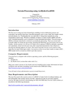
9 The filters discriminatebetween signals based on the frequency range, or bandwidth, of the signal. The three importantbandwidths to consider are the passband, the stopband, and the anti-imaging NI 9237 represents signals within the passband, as quantified primarily by passband rippleand phase nonlinearity. All signals that appear in the alias-free bandwidth are either unaliasedsignals or signals that have been filtered by at least the amount of the stopband signals within the passband have frequency-dependent gain or attenuation. The smallamount of variation in gain with respect to frequency is called the passband flatness. Thedigital filters of the NI 9237 adjust the frequency range of the passband to match the data , the amount of gain or attenuation at a given frequency depends on the data 4. Typical Passband Flatness for the NI 9237 Frequency/Data (dB)StopbandThe filter significantly attenuates all signals above the stopband frequency.
10 The primary goalof the filter is to prevent aliasing. Therefore, the stopband frequency scales precisely with thedata rate. The stopband rejection is the minimum amount of attenuation applied by the filter toall signals with frequencies within the BandwidthAny signals that appear in the alias-free bandwidth are not aliased artifacts of signals at ahigher frequency. The alias-free bandwidth is defined by the ability of the filter to rejectfrequencies above the stopband frequency. The alias-free bandwidth is equal to the data rateminus the stopband 9237 Datasheet | National Instruments | 7 Data RatesThe frequency of a master timebase (fM) controls the data rate (fs) of the NI 9237 . The NI 9237includes an internal master timebase with a frequency of MHz, but the module also canaccept an external master timebase or export its own master timebase. To synchronize the datarate of an NI 9237 with other modules that use master timebases to control sampling, all of themodules must share a single master timebase following equation provides the available data rates of the NI 9237 : = 256 where n is any integer from 1 to , the data rate must remain within the appropriate data rate range.