Transcription of 74 IEEE MICROWAVE AND WIRELESS …
1 74 IEEE MICROWAVE AND WIRELESS COMPONENTS LETTERS, VOL. 15, NO. 2, FEBRUARY 2005A Low loss RF MEMSKu-Band IntegratedSwitched Filter BankIsak C. Reines, Charles L. Goldsmith, Christopher D. Nordquist, Christopher W. Dyck, Garth M. Kraus,Thomas A. Plut, Patrick S. Finnegan, Franklin Austin IV, and Charles T. SullivanAbstract A switched Ku-band filter bank has been developedusing two single-pole triple-throw (SP3T) microelectromechanicalsystems (MEMS) switching networks, and three fixed three-poleend-coupled bandpass filters. A tuning range of from GHz was achieved with a fractional bandwidth of ,and mid-band insertion loss ranging from to Terms End-coupled filters, microelectromechanicalsystems (MEMS) filters, MEMS devices, microstrip filters, RFMEMS, tunable INTRODUCTIONLOW loss , tunable bandpass filters are critical componentsin radio frequency [RF] front ends and transceivers [1].
2 RF microelectromechanical systems (MEMS) enable the con-struction of miniaturized tunable filters that exhibit low loss ,low-power consumption, and excellent linearity compared totheir solid-state counterparts. Integration of RF MEMS filtersin a monolithic MICROWAVE integrated circuit (MMIC) processcan reduce overall system size, weight, and cost, making themattractive for many commercial and military number of researchers have demonstrated tunable band-pass filters at MICROWAVE and millimeter wave frequencies byusing distributed MEMS transmission line (DMTL) designs[2], [3]. DMTL filters are tuned by loading multiple resonatorsections with MEMS capacitive switches that function tochange the phase velocity and electrical length of the resonatorsections, thus tuning the center frequency of the filter.
3 InDMTL filter designs reported to date, the low unloadedofthe resonator sections dominates the high-MEMS varactorsused to tune the filter. This limits the best attainable insertionloss of DMTL filters implemented in a coplanar waveguide(CPW) structure, which typically range between 3 and 4 dB atthrough-band. In addition, the tuning range of DMTL filters is limited by the available tuning of the loading goal of this work is to develop an integrated switchedfilter bank architecture at-band that uses both high-Q fixedManuscript received April 24, 2004; revised July 21, 2004. This work wassupported in part by the Department of Energy s National Nuclear SecurityAdministration under Contract DE-AC04-94AL85000. The review of this letterwas arranged by Associate Editor A. C. Reines, C. D. Nordquist, C.
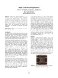
4 W. Dyck, G. M. Kraus, T. A. Plut, and Sullivan are with the Sandia National Laboratories, Albuquerque, NM 87185 USA (e-mail: S. Finnegan is with the L & M Technologies, Albuquerque, NM 87109-5802 L. Goldsmith is with the MEMtronics Corporation, Plano, TX 75075 Austin IV is with The Plus Group, Albuquerque, NM 87112-3800 Object Identifier filter bank based on MEMS SP3T filters, and low loss MEMS metal contactingswitches to reduce overall insertion DMTL filters, this type of architecture is easily scal-able to broader tuning ranges, because the switched filter bankis only limited by the bandwidth of the SP3T work presents a low loss Ku-band switched filter thatis realized with two single-pole triple-throw (SP3T) switchesand a bank of three-pole end-coupled half-wave resonator fil-ters with center frequencies of , , and GHz (Fig.))
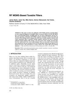
5 1).Series metal contacting MEMS switches in the SP3T switchingnetworks allow for filter selection, while shunt switches sep-arated by a quarter wavelength section of microstrip transmis-sion line increase the isolation between signal paths. In total, theswitched filter bank design incorporates 18 MEMS metal con-tacting switches. In order to avoid MEMS switch yield issues,the SP3T switches were fabricated and tested separately beforebeing incorporated with the filter bank, however, these circuitsare easily implemented in an integrated fashion on a single sub-strate. The overall size of the switched filter bank is mm SP3T SWITCHDESIGNThe layout of the SP3T switching network is shown inFig. 2. The SP3T design requires high isolation (30 dB over14 19 GHz) between the signal paths to reduce unwantedcrosstalk that would otherwise degrade the filter metal contacting switches [4], which are used in botha series and shunt configuration, were modeled as a capacitor10 fF in the up state, and in the down state as a resistorin series with a length of microstrip transmission linewith dimensionsm andm.
6 The MEMS switch has a cantilever thickness of , a spring constantof , and a gap height of The typical pull in voltageof the cantilever switch was 39 V. At the operational voltagewas 55 V and the switching speed was 83s. Since only one1531-1309/$ 2005 IEEEREINESet al.: LOW loss RF MEMS Ku-BAND INTEGRATED SWITCHED FILTER BANK75 Fig. 2. Photomicrograph of SP3T switch is activated to the down state at any time, there arealways two series switches and one shunt switch in the up statethat have a significant effect on the impedance. These switchesyield a 30-fF up-state capacitance that was accounted for withan inductive matching section forming a T-match circuit forgood input and output match [5].Microstrip transmission lines in the SP3T switching networkwere designed for a 50-impedance on a 250-m thick alu-mina substrate Fig.
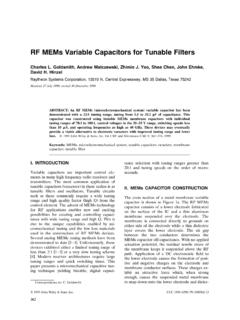
7 3 showsthe inductive matching network and all three series complete model was created for the SP3T switch using Ag-ilent s advanced design system (ADS). Critical microstrip ele-ments such as tee and cross junctions were simulated usingSonnet EM simulator and imported into SP3T switch was tested in lab ambient with a HP 8510 Cnetwork analyzer and cascade RF probe station. Fig. 4 showsthe measured isolation of the SP3T switch with two of the threeoutput ports unterminated. A reduction in the isolation is ob-served since the SP3T switch is designed to exhibit maximumisolation when all three ports are terminated. Fig. 4 also in-cludes ADS simulations with all ports properly terminated andwith two ports unterminated, which matches well with measureddata. Although no data was collected with all ports terminated,the ADS simulation shows that the SP3T switch should exhibitgreater than 29 dB of isolation up to 19 GHz.
8 Measured inser-tion losses of the SP3T switch range between dB at 15 GHzto dB at 18 GHz as shown in Fig. 4. The insertion loss isdominated by radiation losses at the coplanar waveguide to mi-crostrip discontinuity at the input and output, which accountsfor dB at 15 GHz and dB at 18 3. Close up of the SP3T and simulated isolation and insertion loss of the END-COUPLEDFIXEDFILTERDESIGNThe three-polefixed end-coupledfilters have center frequen-cies of , , and GHz, with passband bandwidthsof%. Eachfilter consists of three resonator sectionsthat are approximatelylong at, that are separated byfour coupling capacitors. The length of the resonator sectionsand the values of the coupling capacitors were calculated from[5]. The smaller coupling capacitors in eachfilter were realizedusing transmission line gaps, while the larger coupling capaci-tors were implemented with interdigital structures.
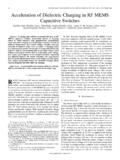
9 To reduce in-sertion losses, eachfilter was fabricated in microstrip with 2-mthick gold lines on a 250-m thick alumina substrate. The inser-tion loss of the was 1 dB, with more than 15 dBof return loss . insertion loss of the was dB,with greater than 15 dB of return loss . The ex-hibited dB if insertion loss and greater than 20 dB of returnloss. The unloadedin each case was greater than SWITCHEDFILTERBANKRESULTSThe switchedfilter bank components were fabricated sepa-rately and assembled on an indium sheet to connect the back-side gold ground planes of the SP3T switches and end-cou-pledfilters. The individual components were wire bonded to-gether to connect the signal paths. Fig. 5 shows the layout ofthe switchedfilter bank. Measured insertion loss and return lossfor the switchedfilter bank are shown in Fig.
10 6. The mid-band76 IEEE MICROWAVE AND WIRELESS COMPONENTS LETTERS, VOL. 15, NO. 2, FEBRUARY 2005 Fig. of the switchedfilter loss and return loss for the switchedfilter loss ranges from dB to 2 dB, with a tuning rangeof centered at GHz. A fractional bandwidth of was measured, with better than 10-dB return loss for allthreefilter states. The return loss of the individualfilters was de-graded by5 dB when connected to the SP3T switches, becausethe MEMS cantilever switches exhibited an up-state capacitanceof 18 fF instead of 10 fF that was used in the initial design. The8-fF capacitance difference was due to an inaccurate up-stateswitch model. The rejection of the end-coupledfilters is reducedat the higher frequencies because the capacitors couple more en-ergy and higher order transmission line resonances come CONCLUSIONThis work presents a Ku-band switchedfilter bank with lowmid-band insertion loss ranging from dB to 2 dB, and re-turn loss greater than 10 dB for all three states.