Transcription of AD5522 (Rev. F) - Analog Devices
1 Quad Parametric Measurement Unit with integrated 16-Bit Level Setting DACs Data Sheet AD5522 Rev. F Document Feedback Information furnished by Analog Devices is believed to be accurate and reliable. However, no responsibility is assumed by Analog Devices for its use, nor for any infringements of patents or other rights of third parties that may result from its use. Specifications subject to change without notice. No license is granted by implication or otherwise under any patent or patent rights of Analog Devices . Trademarks and registered trademarks are the property of their respective owners. One Technology Way, Box 9106, Norwood, MA 02062-9106, Tel: 2008 2018 Analog Devices , Inc. All rights reserved. Technical Support FEATURES Quad parametric measurement unit (PMU) FV, FI, FN (high-Z), MV, MI functions 4 programmable current ranges (internal RSENSE) 5 A, 20 A, 200 A, and 2 mA 1 programmable current range up to 80 mA (external RSENSE) V FV range with asymmetrical operation integrated 16-bit DACs provide programmable levels Gain and offset correction on chip Low capacitance outputs suited to relayless systems On-chip comparators per channel FI voltage clamps and FV current clamps Guard drive amplifier System PMU connections Programmable temperature shutdown SPI- and LV D S-compatible interfaces Compact 80-lead TQFP with exposed pad (top or bottom) APPLICATIONS Automated test equipment (ATE) Per-pin parametric measurement unit Continuity and leakage testing Device power supply Instrumentation Source measure unit (SMU)
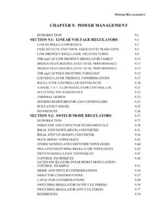
2 Precision measurement FUNCTIONAL BLOCK DIAGRAM 161616 DUTGNDMEASVH[0:3]GUARD[0:3]CGALMSCLKSYNC SDISDOCPOL0/SCLKCPOL2/CPO0 CPOH2/CPO1 CPOL3/CPO2 CPOH3/CPO3 SERIALINTERFACECPOH0/SDICPOL1/SYNCCPOH1/ SDOSPI/LVDSRESETBUSY16 CLAMP ANDGUARDALARMTEMPSENSORPOWER-ONRESETGUAR DIN[0:3]/DUTGND[0:3]DUTEXTERNALRSENSE(CU RRENTSUPTO 80mA)EXTMEASIH[0:3]EXTMEASIL[0:3]FOH[0:3 ]EXTFOH[0:3]CFF[0:3]FINCLHCLLAVSSAVDDAGN D+ MEASOUT[0:3] 4 DGNDCPHCOMPARATORCCOMP[0:3]LOADCPLINTERN AL RANGE SELECT( 5 A, 20 A, 200 A, 2mA) ++ + +++RSENSE ++1616161616 VREFSYS_FORCESYS_SENSEDVCC16X1 REGC REGM REG1616161616161616-BITFIN DAC 5 or 10 2 1 TMPALMAGNDREFGND16-BITCLH DACMEASOUTMUXAND GAIN 1/ REGC REGM REGX1 REGC REGM REG16 216161616X1 REGC REGM REG 6 6 OFFSET DAC16-BITOFFSET DACTO ALL DACOUTPUTAMPLIFIERSFORCEAMPLIFIER16-BITC LL DAC16-BITCPH DAC16-BITCPL DACSW1SW2SW3SW460 SW6SW5SW9SW8SW10SW11 MEASUREVOLT AGEIN-AMPMEASURECURRENTIN-AMPTEMPSENSORT OMEASOUTMUXSW12X1 REGC REGM REG 6X2 REGX2 REGX2 REG 6X2 REGX2 REG 6 6 2 2 AGNDEN1k GUARDAMPSW13SW14 AGND10k SW15SW16 DUTGNDVMIDTOCENTERI RANGE+ 06197-001 AGNDSW74k 2k MEASVH(Hi-Z)4k Figure 1.
3 AD5522 Data Sheet Rev. F | Page 2 of 64 TABLE OF CONTENTS Features .. 1 Applications .. 1 Functional Block Diagram .. 1 Revision History .. 3 General Description .. 4 Specifications .. 6 Timing Characteristics .. 11 Absolute Maximum Ratings .. 15 Thermal Resistance .. 15 ESD Caution .. 15 Pin Configurations and Function Descriptions .. 16 Typical Performance Characteristics .. 22 Terminology .. 29 Theory of Operation .. 30 Force Amplifier .. 30 Comparators .. 30 Clamps .. 30 Current Range Selection .. 31 High Current Ranges .. 31 Measure Current 32 VMID Voltage .. 32 Choosing Power Supply Rails .. 33 Measure Output (MEASOUTx Pins).. 33 Device Under Test Ground (DUTGND).. 33 Guard Amplifier .. 34 Compensation Capacitors .. 34 System Force and Sense Switches .. 35 Temperature Sensor .. 35 DAC Levels .. 36 Offset DAC .. 36 Gain and Offset Registers.
4 36 Cached X2 Registers .. 37 Reference Voltage (VREF) .. 37 Reference Selection .. 37 38 Additional Calibration .. 39 System Level Calibration .. 39 Circuit Operation .. 40 Force Voltage (FV) Mode .. 40 Force Current (FI) Mode .. 41 Serial Interface .. 42 SPI Interface .. 42 LVDS 42 Serial Interface Write Mode .. 42 RESET Function .. 42 BUSY and LOAD Functions .. 42 Register Update Rates .. 44 Register Selection .. 44 Write System Control Register .. 46 Write PMU Register .. 48 Write DAC Register .. 50 Read Registers .. 53 Readback of System Control 54 Readback of PMU Register .. 55 Readback of Comparator Status Register .. 56 Readback of Alarm Status Register .. 56 Readback of DAC Register .. 57 Applications Information .. 58 Power-On Default .. 58 Setting Up the Device on Power-On .. 58 Changing Modes .. 59 Required External Components .. 59 Power Supply Decoupling.
5 60 Power Supply Sequencing .. 60 Typical Application for the AD5522 .. 60 Outline Dimensions .. 62 Ordering Guide .. 63 Data Sheet AD5522 Rev. F | Page 3 of 64 REVISION HISTORY 6/2018 Rev. E to Rev. F Changes to Table 1 .. 7 Changes to Table 2 .. 11 Changes to Figure 5 .. 13 Changes to Choosing Power Supply Rails Section and Note 2, Table 10 .. 33 Moved Table 11 .. 34 Changes to MV Transfer Function, Table 11 and Note 3, Table 11 .. 34 Changes to Table 39 .. 60 Changes to Ordering Guide .. 63 5/2012 Rev. D to Rev. E Change to MV Transfer Function, Table 11 .. 33 2/2011 Rev. C to Rev. D Changes to Measure Current, Gain Error Tempco Parameter .. 6 Changes to Force Current, Common Mode Error (Gain = 5) and Common Mode Error (Gain = 10) Parameters .. 7 Changes to Figure 5 .. 13 Changes to Figure 6 .. 14 Changes to Figure 15 .. 22 Changes to High Current Ranges Section.
6 31 Changes to Gain and Offset Registers Section .. 36 Changes to Endnote 1 in Table 17 and Figure 56 .. 43 Changes to Register Update Rates and Figure 57 .. 44 Changes to Bit 15 to Bit 0 Description in Table 28 .. 50 5/2010 Rev. B to Rev. C Changes to Compensation Capacitors Section .. 34 Changes to Gain and Offset Registers Section .. 36 Changes to Table 14 and Reducing Zero-Scale Error Section .. 38 Changes to Serial Interface Write Mode Section and BUSYEE and LOADEE Functions Section .. 42 Changes to Table 17 .. 43 Added Table 18; Renumbered Sequentially .. 43 Changes to Register Update Rates Section .. 44 Changes to Table 23 .. 46 Changes to Table 31 .. 54 10/2009 Rev. A to Rev. B Changes to Table 1 .. 6 Changes to Table 2 .. 11 Added Figure 13 and Figure 15; Renumbered Sequentially .. 22 Added Figure 16 .. 23 Changes to Figure 21 .. 23 Changes to Clamps Section.
7 30 Changes to Table 22, Bit 21 to Bit 18 Description .. 44 Changes to Table 25, Bit 9 Description .. 47 Changes to Table 28 .. 49 Changes to Figure 59 .. 59 10/2008 Rev. 0 to Rev. A Changes to Table 1 .. 6 Change to 4 DAC X1 Parameter, Table 2 .. 11 Changes to Table 3 .. 12 Change to Reflow Soldering Parameter, Table 4 .. 15 Changes to Figure 18, Figure 19, Figure 20, and Figure 21 .. 23 Changes to Figure 25 .. 24 Changes to Force Amplifier Section .. 29 Changes to Clamps Section .. 29 Changes to High Current Ranges Section .. 30 Changes to Choosing Power Supply Rails Section .. 32 Changes to Compensation Capacitors Section .. 33 Added Table 14, Renumbered Tables Sequentially .. 36 Changes to Reference Selection Example .. 36 Changes to Table 15 and BUSYEE and LOADEE Functions Section .. 40 Changes to Table 17 and Register Update Rates Section .. 41 Added Table 38.
8 57 Changes to Ordering Guide .. 60 7/2008 Revision 0: Initial Version AD5522 Data Sheet Rev. F | Page 4 of 64 GENERAL DESCRIPTION The AD5522 is a high performance, highly integrated parametric measurement unit consisting of four independent channels. Each per-pin parametric measurement unit (PPMU) channel includes five 16-bit, voltage output DACs that set the programmable input levels for the force voltage inputs, clamp inputs, and comparator inputs (high and low). Five programmable force and measure current ranges are available, ranging from 5 A to 80 mA. Four of these ranges use on-chip sense resistors; one high current range up to 80 mA is available per channel using off-chip sense resistors. Currents in excess of 80 mA require an external ampli-fier. Low capacitance DUT connections (FOHx and EXTFOHx) ensure that the device is suited to relayless test systems.
9 The PMU functions are controlled via a simple 3-wire serial interface compatible with SPI, QSPI , MICROWIRE , and DSP interface standards. Interface clocks of 50 MHz allow fast updating of modes. The low voltage differential signaling (LV D S) interface protocol at 83 MHz is also supported. Comparator outputs are provided per channel for device go-no-go testing and character-ization. Control registers allow the user to easily change force or measure conditions, DAC levels, and selected current ranges. The SDO (serial data output) pin allows the user to read back information for diagnostic purposes. Data Sheet AD5522 Rev. F | Page 5 of 64 DUTGNDGUARD0 CPOL0/SCLKCPOH0/SDIGUARDIN0/DUTGND0 DUTSYS_FORCESYS_SENSECGALMCPOL2/CPO0 CPOL1/SYNCCPOH1/SDOCPOH2/CPO1 TMPALMCLAMP ANDGUARDALARMTEMPSENSORTOMEASOUTMUXMEASV H3 FOH3 EXTMEASIH3 EXTMEASIL3CH1CH0CH2CH3 FOH2 EXTFOH2 EXTMEASIH2 EXTMEASIL2 MEASVH2 GUARD2 MEASVH1 EXTMEASIL1 FOH1 EXTFOH1 CFF1 CFF3 CFF2 EXTMEASIH1 GUARD1 GUARDIN1/DUTGND1 MEASOUT1 CCOMP1 CCOMP2 MEASOUT2 AGNDAGNDDUTGND161616 MEASVH0 CPOL3/CPO2 CPOH3/CPO3 SPI/LVDSEXTERNALRSENSE(CURRENTSUP TO 80mA)
10 EXTMEASIH0 EXTMEASIL0 FOH0 EXTFOH0 CFF0 FINCLHCLLAVSSAVDDAGND+ MEASOUT0 DGNDCPHCOMPARATORCCOMP0 CPL ++ + +++RSENSE ++1616161616 VREFDVCC16X1 REGC REGM REG1616161616161616-BITFIN DAC 5 OR 10 2 1 AGNDREFGND16-BITCLH DACMEASOUTMUX AND GAIN 1/ REGC REGM REGX1 REGC REGM REG 216161616X1 REGC REGM REG 6 6 OFFSET DACFORCEAMPLIFIER16-BITCLL DAC16-BITCPH DAC16-BITCPL DACSW1SW2SW3SW4SW6SW9SW8SW5SW10SW11 MEASUREVOLTAGEIN-AMPMEASURECURRENTIN-AMP TEMPSENSORSW12X1 REGC REGM REG 6X2 REGX2 REGX2 REG 6X2 REGX2 REG 6 6 2 2 AGNDENGUARD AMPSW13SW14 AGND10k SW15SW16 DUTGNDVMID TOCENTERI RANGEAGND10k AGND10k + GUARDIN2/DUTGND2 EXTFOH3161616 GUARDIN3/DUTGND3 GUARD3 DUTEXTERNALRSENSE(CURRENTSUP TO 80mA)FINCLHCLLAGND+ MEASOUT3 CPHCOMPARATORCPLINTERNAL RANGESELECT( 5 A, 20 A, 200 A, 2mA)INTERNAL RANGESELECT( 5 A, 20 A, 200 A, 2mA) ++ + +++RSENSE ++1616161616 CCOMP316X1 REGC REGM REG1616161616161616-BITFIN DACx5 or x10 2x1 AGND16-BITCLH DACMEASOUTMUX AND GAINx1 REGC REGM REGX1 REGC REGM REG 216161616X1 REGC REGM REG 6 6 OFFSET DACFORCEAMPLIFIER16-BITCLL DAC16-BITCPH DAC16-BITCPL DACSW1SW2SW3SW4SW6SW5SW9SW8SW10SW11 MEASUREVOLTAGEIN-AMPMEASURECURRENTIN-AMP TEMPSENSORSW12C REGM REG 6X2 REGX2 REGX2 REG 6X2 REGX2 REG 6 6 2 2 ENGUARD AMPSW13SW14SW15SW15aSW16 DUTGNDVMID TOCENTERI RANGE+ 06197-002 MUXMUXSCLKSYNCSDISDOSERIALINTERFACERESET BUSY16 POWER-ONRESETLOAD1616-BITOFFSET DACTO ALL DACOUTPUTAMPLIFIERSX1 REGAGNDSW74k 2k 2k MEASVH(Hi-Z)AGNDMEASVH(Hi-Z)4k SW74k 4k Figure 2.