Transcription of AD8131 Low Cost, High Speed Differential Driver Data Sheet ...
1 Low Cost, High Speed Differential Driver AD8131 . FEATURES FUNCTIONAL BLOCK DIAGRAM. High Speed 400 MHz, 3 dB full power bandwidth DIN 1 8 +DIN. 750 750 . 2000 V/ s slew rate VOCM 2 7 NC. Fixed gain of 2 with no external components V+ 3 6 V . Internal common-mode feedback to improve gain and phase . balance: 60 dB @ 10 MHz +OUT 4 5 OUT. Separate input to set the common-mode output voltage AD8131 . 01072-001. Low distortion: 68 dB SFDR @ 5 MHz 200 load NC = NO CONNECT. Power supply range + V to 5 V. Figure 1. APPLICATIONS. Video line Driver Digital line Driver Low power Differential ADC Driver Differential in/out level shifting single - ended input to Differential output Driver GENERAL DESCRIPTION.
2 The AD8131 is a Differential or single - ended input to 20. Differential output Driver requiring no external components for VOUT, dm = 2V p-p VOUT, cm/ VOUT, dm a fixed gain of 2. The AD8131 is a major advancement over op 30. amps for driving signals over long lines or for driving BALANCE ERROR (dB). Differential input ADCs. The AD8131 has a unique internal 40. feedback feature that provides output gain and phase matching that are balanced to 60 dB at 10 MHz, reducing radiated EMI 50. and suppressing harmonics. Manufactured on the Analog VS = +5V. Devices, Inc. next generation XFCB bipolar process, the 60. AD8131 has a 3 dB bandwidth of 400 MHz and delivers a Differential signal with very low harmonic distortion.
3 70. VS = 5V. 01072-002. The AD8131 is a Differential Driver for the transmission of 80. 1 10 100 1000. high- Speed signals over low-cost twisted pair or coax cables. FREQUENCY (MHz). The AD8131 can be used for either analog or digital video Figure 2. Output Balance Error vs. Frequency signals or for other high- Speed data transmission. The AD8131 . Driver is capable of driving either Cat3 or Cat5 twisted pair or The AD8131 's Differential output also helps balance the input coax with minimal line attenuation. The AD8131 has for Differential ADCs, optimizing the distortion performance of considerable cost and performance improvements over discrete the ADCs. The common-mode level of the Differential output is line Driver solutions.
4 Adjustable by a voltage on the VOCM pin, easily level-shifting the input signals for driving single -supply ADCs with dual supply The AD8131 can replace transformers in a variety of applications, signals. Fast overload recovery preserves sampling accuracy. preserving low frequency and dc information. The AD8131 does not have the susceptibility to magnetic interference and hysteresis The AD8131 is available in both SOIC and MSOP packages for of transformers. It is smaller, easier to work with, and has the high operation over 40 C to +125 C. reliability associated with ICs. Rev. B. Information furnished by Analog Devices is believed to be accurate and reliable. However, no responsibility is assumed by Analog Devices for its use, nor for any infringements of patents or other rights of third parties that may result from its use.
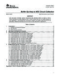
5 Specifications subject to change without notice. No license is granted by implication One Technology Way, Box 9106, Norwood, MA 02062-9106, or otherwise under any patent or patent rights of Analog Devices. Trademarks and Tel: registered trademarks are the property of their respective owners. Fax: 2005 Analog Devices, Inc. All rights reserved. AD8131 . TABLE OF CONTENTS. 3 Estimating the Output Noise Voltage .. 16. DIN to OUT 3 Calculating the Input Impedance of an Application 16. VOCM to OUT Specifications .. 4. Input Common-Mode Voltage Range in DIN to OUT 5 single -Supply Applications .. 17. VOCM to OUT Specifications .. 6 Setting the Output Common-Mode Voltage .. 17.
6 Absolute Maximum 7 Driving a Capacitive 17. ESD 7 18. Pin Configuration and Function 8 Twisted-Pair Line 18. Typical Performance Characteristics .. 9 3 V Supply Differential A-to-D 18. Operational 15 Unity-Gain, single - ended -to- Differential Driver .. 19. Theory of Operation .. 16 Outline Dimensions .. 20. Analyzing an Application 16 Ordering Guide .. 20. Closed-Loop Gain .. 16. REVISION HISTORY. 6/05 Rev. A to Rev. B. Updated Changed Upper Operating Limit ..Universal Changes to Ordering Guide .. 20. Rev. B | Page 2 of 20. AD8131 . SPECIFICATIONS. DIN TO OUT SPECIFICATIONS. 25 C, VS = 5 V, VOCM = 0 V, G = 2, RL, dm = 200 , unless otherwise noted. Refer to Figure 5 and Figure 39 for test setup and label descriptions.
7 All specifications refer to single - ended input and Differential outputs, unless otherwise noted. Table 1. Parameter Conditions Min Typ Max Unit DYNAMIC PERFORMANCE. 3 dB Large Signal Bandwidth VOUT = 2 V p-p 400 MHz 3 dB Small Signal Bandwidth VOUT = V p-p 320 MHz Bandwidth for dB Flatness VOUT = V p-p 85 MHz Slew Rate VOUT = 2 V p-p, 10% to 90% 2000 V/ s Settling Time , VOUT = 2 V p-p 14 ns Overdrive Recovery Time VIN = 5 V to 0 V Step 5 ns NOISE/HARMONIC PERFORMANCE. Second Harmonic VOUT = 2 V p-p, 5 MHz, RL, dm = 200 68 dBc VOUT = 2 V p-p, 20 MHz, RL, dm = 200 63 dBc VOUT = 2 V p-p, 5 MHz, RL, dm = 800 95 dBc VOUT = 2 V p-p, 20 MHz, RL, dm = 800 79 dBc Third Harmonic VOUT = 2 V p-p, 5 MHz, RL, dm = 200 94 dBc VOUT = 2 V p-p, 20 MHz, RL, dm = 200 70 dBc VOUT = 2 V p-p, 5 MHz, RL, dm = 800 101 dBc VOUT = 2 V p-p, 20 MHz, RL, dm = 800 77 dBc IMD 20 MHz, RL, dm = 800 54 dBc IP3 20 MHz, RL, dm = 800 30 dBm Voltage Noise (RTO) f = 20 MHz 25 nV/ Hz Differential Gain Error NTSC, RL, dm = 150 %.
8 Differential Phase Error NTSC, RL, dm = 150 degrees INPUT CHARACTERISTICS. Input Resistance single - ended input k . Differential input k . Input Capacitance 1 pF. Input Common-Mode Voltage to + V. CMRR VOUT, dm/ VIN, cm; VIN, cm = V 70 dB. OUTPUT CHARACTERISTICS. Offset Voltage (RTO) VOS, dm = VOUT, dm; VDIN+ = VDIN = VOCM = 0 V 2 7 mV. TMIN to TMAX variation 8 V/ C. VOCM = float 4 mV. TMIN to TMAX variation 10 V/ C. Output Voltage Swing Maximum VOUT; single - ended output to + V. Linear Output Current 60 mA. Gain VOUT, dm/ VIN, dm; VIN, dm = V 2 V/V. Output Balance Error VOUT, cm/ VOUT, dm; VOUT, dm = 1 V 70 dB. Rev. B | Page 3 of 20. AD8131 . VOCM TO OUT SPECIFICATIONS.
9 25 C, VS = 5 V, VOCM = 0 V, G = 2, RL, dm = 200 , unless otherwise noted. Refer to Figure 5 and Figure 39 for test setup and label descriptions. All specifications refer to single - ended input and Differential outputs, unless otherwise noted. Table 2. Parameter Conditions Min Typ Max Unit DYNAMIC PERFORMANCE. 3 dB Bandwidth VOCM = 600 mV 210 MHz Slew Rate VOCM = 1 V to +1 V 500 V/ s DC PERFORMANCE. Input Voltage Range V. Input Resistance 120 k . Input Offset Voltage VOS, cm = VOUT, cm; VDIN+ = VDIN = VOCM = 0 V 7 mV. VOCM = float mV. Input Bias Current A. VOCM CMRR VOUT, dm/ VOCM; VOCM = V 60 dB. Gain VOUT, cm/ VOCM; VOCM = 1 V 1 V/V. POWER SUPPLY. Operating Range V. Quiescent Current VDIN+ = VDIN = VOCM = 0 V mA.
10 TMIN to TMAX variation 25 A/ C. Power Supply Rejection Ratio VOUT, dm/ VS; VS = 1 V 70 56 dB. OPERATING TEMPERATURE RANGE 40 +125 C. Rev. B | Page 4 of 20. AD8131 . DIN TO OUT SPECIFICATIONS. 25 C, VS = 5 V, VOCM = V, G = 2, RL, dm = 200 , unless otherwise noted. Refer to Figure 5 and Figure 39 for test setup and label descriptions. All specifications refer to single - ended input and Differential outputs, unless otherwise noted. Table 3. Parameter Conditions Min Typ Max Unit DYNAMIC PERFORMANCE. 3 dB Large Signal Bandwidth VOUT = 2 V p-p 385 MHz 3 dB Small Signal Bandwidth VOUT = V p-p 285 MHz Bandwidth for dB Flatness VOUT = V p-p 65 MHz Slew Rate VOUT = 2 V p-p, 10% to 90% 1600 V/ s Settling Time , VOUT = 2 V p-p 18 ns Overdrive Recovery Time VIN = 5 V to 0 V Step 5 ns NOISE/HARMONIC PERFORMANCE.