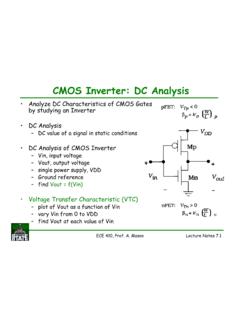
Transcription of AN118 - AN118 - High Voltage, Low Noise, DC/DC Converters
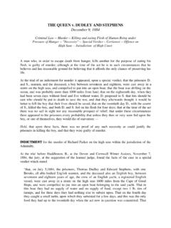
1 Application Note 118AN118-1an118fbMarch 2008transformers originally intended for LCD display backlight service are readily available. These transformers are mul-tiply sourced, well proven and competitively priced. Figure 1 s resonant Royer topology achieves 100 VP-P noise at 250V output by minimizing high frequency harmonic in the power drive stage. The self oscillating resonant Royer circuitry is composed of Q2, Q3, C1, T1 and L1. Current flow through L1 causes the T1, Q2, Q3, C1 circuitry to oscillate in resonant fashion, supplying sine Figure 1. Current Fed Resonant Royer Converter Produces high Voltage Output. A1 Biases Q1 Current Sink, Enforcing Output Voltage Stabilizing Feedback Loop. A1 s F 1k Network Phase Leads Output Filter, Optimizing Transient Response. D5-D6, Low Leakage Clamps, Protect A1 IntroductionPhotomultipliers (PMT), avalanche photodiodes (APD), ultrasonic transducers, capacitance microphones, radia-tion detectors and similar devices require high voltage, low current bias.
2 Additionally, the high voltage must be pristinely free of noise; well under a millivolt is a common requirement with a few hundred microvolts sometimes necessary. Normally, switching regulator configurations cannot achieve this performance level without employing special techniques. One aid to achieving low noise is that load currents rarely exceed 5mA. This freedom permits output filtering methods that are usually impractical. This publication describes a variety of circuits featuring outputs from 200V to 1000V with output noise below 100 V measured in a 100 MHz bandwidth. Special techniques enable this performance, most notably power stages optimized to minimize high frequency harmonic content. Although sophisticated, all examples presented utilize standard, commercially available magnetics no custom components are required. This provision is intended to assist the user in quickly arriving at a produceable design.
3 Circuits and their descriptions are presented beginning with the next ink. BEFORE PROCEEDING ANY FURTHER, THE READER IS WARNED THAT CAUTION MUST BE USED IN THE CONSTRUCTION, TESTING AND USE OF THE TEXT S CIRCUITS. high VOLTAGE, LETHAL POTENTIALS ARE PRESENT IN THESE CIRCUITS. EXTREME CAUTION MUST BE USED IN WORKING WITH, AND MAKING CONNECTIONS TO, THESE CIRCUITS. REPEAT: THESE CIRCUITS CONTAIN DANGEROUS, high VOLTAGE POTENTIALS. USE CAUTION. Resonant Royer Based ConvertersThe resonant Royer topology is well suited to low noise operation due to its sinosoidal power delivery1. Addition-ally, the resonant Royer is particularly attractive because high Voltage, Low Noise, DC/DC ConvertersA Kilovolt with 100 Microvolts of NoiseJim WilliamsL, LT, LTC and LTM are registered trademarks of Linear Technology Corporation. All other trademarks are the property of their respective F011 F, 400V1 F, 400V + F400V1k250 VOUT1M*1kOUTPUTADJUST499 *430k430k10kL1250 HIRLRO24Q1A1Q3Q2820 Fx25VC1 VREF = !
4 Lethal Potentials Present See Text = ZDT1048 DUALL1 = CTX250-4, COILTRONICST1 = 210605R, COILTRONICS1 F = WIMA F = WIMA MKP-2D1-D4 = TOSHIBA DUAL DIODE 1SS306. CONNECT EACH UNIT IN = 2N4393* = 1% METAL FILM RESISTORNote 1. This publication sacrifices academic completeness for focus on the title subject. As such, operating details of the various switching regulator architectures utilized are not covered. Readers desiring background tutorial are directed to the References. Resonant Royer theory appears in Reference Note 118AN118-2an118fbwave drive to T1 s primary with resultant sine-like high voltage appearing across the s rectified and filtered output is fed back to amplifier-reference A1 which biases the Q1 current sink, completing a control loop around the Royer converter. L1 ensures that Q1 maintains constant current at high frequency.
5 Milliampere level output current allows the 10k resistor in the output filter. This greatly aids filter performance with minimal power The RC path to A1 s negative input combines with the F capacitor to compensate A1 s loop. D5 and D6, low leakage clamps, protect A1 during start-up and transient events. Although Figure 2 s collector waveforms are distorted, no high frequency content is circuit s low harmonic content combined with the RC output filter produces a transcendently clean output. Output noise (Figure 3) is just discernible in the monitoring instrumentation s 100 V noise 4 s variant of Figure 1 maintains 100 V output noise while extending input supply range to 32V. Q1 may require heat sinking at high input supply voltage. Converter and loop operation is as before although compensation com-ponents are re-established to accommodate the LT1431 control element.
6 Figure 2. Resonant Royer Collector Waveforms Are Distorted Sinosoids; No high Frequency Content is PresentFigure 3. Figure 1 s Output Noise is Just Discernable in Monitoring Instrumentation s 100 V Noise Floor20 s/DIVAN118 F02A = 5V/DIVB = 5V/DIV10 s/DIVAN118 F03100 V/DIVAC COUPLEDAN118 F041 F, 400V1 F, F400V1k250 VOUT1M* *L1250 H5VT110kD1-D410654123LT1431+ F1k5VD5D65 VIRLRO24Q1 DANGER! Lethal Potentials Present See Text = ZDT1048 DUALL1 = CTX250-4, COILTRONICST1 = 210605R, COILTRONICS1 F = WIMA F = WIMA MKP-2D1-D4 = TOSHIBA DUAL DIODE 1SS306. CONNECT EACH UNIT IN = 1N4148* = 1% METAL FILM RESISTOR820 Figure 4. LT1431 Regulator Based Variant of Figure 1 Maintains 100 V Output Noise While Extending Input Supply Range to 32V. Q1 May Require Heat Sinking at high Input Supply VoltagesNote 2. As previously mentioned, low current requirements permit certain freedoms in the output filter and feedback network.
7 See Appendix A for examples and discussion. Note 3. Measurement technique and instrumentation choice for faithful low level noise measurement requires diligence. See Appendices B through E for practical Note 118AN118-3an118fbSwitched Current Source Based Resonant Royer ConvertersThe previous resonant Royer examples utilize linear con-trol of converter current to furnish harmonic free drive. The trade off is decreased efficiency, particularly as input voltage scales. Improved efficiency is possible by employ-ing switched mode current drive to the Royer converter. Unfortunately, such switched drive usually introduces noise. As will be shown, this undesirable consequence can be countered. Figure 5 replaces the linearly operated current sink with a switching regulator. The Royer converter and its loop are as before; Figure 6 s transistor collector waveshape (trace A) is similar to the other circuits.
8 The high speed, switch mode current sink drive (trace B) efficiently feeds L1. This switched operation improves efficiency but degrades output noise. Figure 7 shows switching regulator harmonic clearly responsible for 3mV peak to peak output noise about 30 times greater than the linearly operated circuits. Careful examination of Figure 7 reveals almost no Royer based residue. The noise is dominated by switching regulator artifacts. Eliminating this switching regulator originated noise while maintaining efficiency requires special circuitry but is readily achievable. AN118 F051 F, 400V1 F, *L1250 Fx2D6D55 VVCRT1 F20k5V1M1N5817 DANGER! Lethal Potentials Present See Text = ZDT1048 DUALL1 = CTX250-4, COILTRONICST1 = 210605R, COILTRONICS1 F = WIMA F = WIMA MKP-2D1-D4 = TOSHIBA DUAL DIODE 1SS306. CONNECT EACH UNIT IN = 1N4148* = 1% METAL FILM RESISTOR820 Figure 5.
9 Replacing Linearly Operated Current Sink with Switching Regulator Minimizes Heating Although Output Noise IncreasesA = 20 s/DIVB = 1 s/DIV(TRIGGERS ASYNCRONOUS) AN118 F06A = 5V/DIVB = 5V/DIV500ns/DIVAN118 F07A = 1mV/DIVAC COUPLEDF igure 6. Resonant Royer Collector Waveshape (Trace A) is Similar to Previous Circuits. high Speed, Switched Mode Current Sink Drive (Trace B) Efficiency Feeds L1 Figure 7. Switching Regulator Harmonic Results in 3mVP-P Output NoiseApplication Note 118AN118-4an118fbLow Noise Switching Regulator Driven Resonant Royer ConvertersFigure 8 examplifies the aforementioned special circuitry . The resonant Royer converter and its loop are reminis-cent of previous circuits. The fundamental difference is the LT1534 switching regulator which utilizes controlled transition times to retard high frequency harmonic while maintaining efficiency. This approach blends switching and linear current sink benefits4.
10 Voltage and current transi-tion rate, set by RV and RI respectively, is a compromise between efficiency and noise 4. As stated, this forum must suffer brevity to maintain focus. The LT1534 s controlled transition time operation mandates further study. See Reference 9 s Royer collector waveshape (trace A) is nearly identical to the one produced by Figure 5 s circuit. Trace B, depicting LT1534 controlled transition times, markedly departs from its Figure 5 counterpart. These controlled transition times dramatically reduce output noise (Figure 10) to 150 VP-P a 20x improvement vs Figure 7 s LTC3401 based results. AN118 F081 F, 400V1 F, F400V100k250 VOUT1M* *L1L228nH5VT11kD1-D410654123LT1534 COL+ *DANGER! Lethal Potentials Present See Text = ZDT1048 DUALL2 = COILCRAFT B08TL1 = CTX250-4, COILTRONICST1 = 210605R, COILTRONICS1 F = WIMA F = WIMA MKP-2D1-D4 = TOSHIBA DUAL DIODE 1SS306.