Transcription of AN2686 Ethernet Compliance Testing for 10BASE-T, …
1 AN2686 . Ethernet Compliance Testing for 10 BASE-T, 100 BASE-TX, and 1000 BASE-T. Author: John MacKay Microchip Technology Inc. INTRODUCTION. The IEEE Ethernet Compliance Testing encompasses a wide range of tests that utilize different waveforms for the various device speeds: 10 BASE-T: Four waveforms (link pulse /idle, pseudo-random, all ones, and arbitrary waveform signal). 100 BASE-TX: Two waveforms (transmit scrambled idle and arbitrary waveform signal). 1000 BASE-T: Five waveforms (four test mode 1-4 waveforms and arbitrary waveform signal).
2 The register settings apply to the PHY registers for most of Microchip's Ethernet products. Note: The test setup and figures are with a Tektronix scope, TDSET3 Ethernet Compliance Software, and TF-GBE. test fixture board. The Twisted Pair Model (TPM) is on the test fixture board. 10 BASE-T Compliance Testing . The 10 BASE-T Compliance tests are: Link pulse Testing Medium Attachment Unit (MAU). TP_IDL. Jitter Differential Voltage Harmonics Transmitter Return Loss Receiver Return Loss Common-Mode Voltage Link pulse Testing and TP_IDL are tested with and without the Twisted Pair Model.
3 Each test section below provides the test description, test setup details, and pass criteria. For 10 BASE-T test data transmission (pseudo-random and all ones patterns) on KSZ switches, KSZ Gigabit PHYs and LAN PHYs (other than LAN78xx which can generate test patterns itself), use the link partner (set to forced 10 BASE-T). to transmit the signal to the device under test (DUT) and enable remote loopback on the DUT. For 10 BASE-T test data transmission (pseudo-random and all ones patterns) on KSZ80xx PHYs, the PHY is connected to the MAC of a switch via MII/RMII connection.
4 The link partner transmits the test signal to the switch's PHY port and through the MII/RMII to the DUT's PHY port. Link pulse Testing This is a test of the 10 BASE-T Link pulse signal integrity. For link pulse Testing without Twisted Pair Model, the DUT is connected to the DUT port for the 10 BASE-T Parametric/. Template Test (some boards may add without Twisted Pair Model'), and the oscilloscope probe is attached to the test jumper. For link pulse Testing with Twisted Pair Model, the DUT is connected to the DUT port for the 10 BASE-T Parametric/Tem- plate Test with Twisted Pair Model, and the oscilloscope probe is attached to the test jumper after load selection.
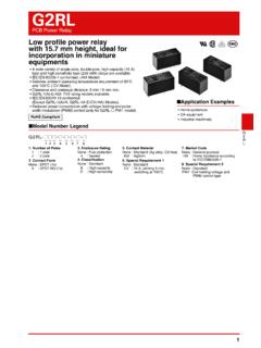
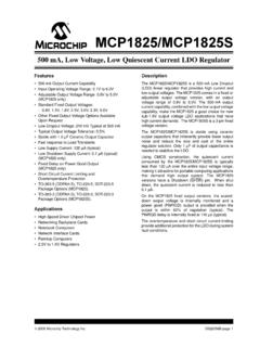
5 To configure the DUT for link pulse Testing , refer to 10 BASE-T Link pulse Setting on any part for register settings. Pass specification is based on the Link pulse remaining inside the mask for both the head and the tail. 2018 Microchip Technology Inc. DS00002686A-page 1. AN2686 . FIGURE 1: 10 BASE-T LINK pulse WITHOUT TWISTED PAIR MODEL. FIGURE 2: 10 BASE-T LINK pulse WITH TWISTED PAIR MODEL. DS00002686A-page 2 2018 Microchip Technology Inc. AN2686 . Medium Attachment Unit (MAU). This is a test of the MAU of the PHY. The DUT is connected to the DUT port for the 10 BASE-T Parametric/Template Test with Twisted Pair Model, and the oscilloscope probe is attached to the test jumper.
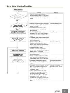
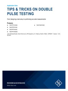
6 To configure the DUT for MAU. Testing , refer to the 10 BASE-T Loopback Mode on KSZ parts register settings. For LAN78xx, refer to 10 BASE-T. Pseudo-Random Signal Setting LAN78xx for register settings. On the oscilloscope, set for internal or external. Short the 100-ohm jumper on the test board. Pass specification is based on the signal remaining inside the mask. FIGURE 3: 10 BASE-T MAU - EXTERNAL. FIGURE 4: 10 BASE-T MAU - INTERNAL. 2018 Microchip Technology Inc. DS00002686A-page 3. AN2686 . TP_IDL. This is a test of the 10 BASE-T TP_IDL signal at the end of a data packet, which signals the start of the idle period.
7 For TP_IDL without Twisted Pair Module, the DUT is connected to the DUT port for the 10 BASE-T Parametric/Template Test (some boards may add without Twisted Pair Model'), and the oscilloscope probe is attached to the test jumper. For TP_IDL with Twisted Pair Module, the DUT is connected to the DUT port for the 10 BASE-T Parametric/Template Test with Twisted Pair Module, and the oscilloscope probe is attached to the test jumper. To configure the DUT for TP_IDL Testing , refer to the 10 BASE-T Loopback Mode on KSZ parts register settings.
8 For LAN78xx, refer to 10 BASE-T Pseudo-Random Signal Setting LAN78xx for register settings. Pass specification is based on the TD_IPL remaining inside the mask. FIGURE 5: 10 BASE-T TP_IDL WITHOUT TWISTED PAIR MODEL. FIGURE 6: 10 BASE-T TP_IDL WITH TWISTED PAIR MODEL. DS00002686A-page 4 2018 Microchip Technology Inc. AN2686 . Jitter This is a test of the 10 BASE-T link data pattern for jitter. For jitter without Twisted Pair Module: The DUT is connected the DUT port for the 10 BASE-T Parametric/Template Test (some boards may add without Twisted Pair Model'), and the oscilloscope probe is attached to the test jumper.
9 Pass specification is based on the jitter at both 8 bit times and bit times crossovers less than 20 ns. For jitter with Twisted Pair Module: The DUT is connected to the DUT port for the 10 BASE-T Parametric/Template Test with Twisted Pair Model, and the oscilloscope probe is attached to the test jumper. Pass specification is based on the jitter at both 8 bit times and bit times crossovers less than 11 ns. The Link Partner is connected to the other Ethernet port. To configure the DUT for jitter Testing , refer to the 10 BASE-T. Loopback Mode on KSZ parts register settings.
10 For LAN78xx, refer to 10 BASE-T Pseudo-Random Signal Setting . LAN78xx for register settings. FIGURE 7: 10 BASE-T BIT TIME JITTER WITHOUT TWISTED PAIR MODEL. FIGURE 8: 10 BASE-T BIT TIME JITTER WITH TWISTED PAIR MODEL. 2018 Microchip Technology Inc. DS00002686A-page 5. AN2686 . Differential Voltage This is a test of the peak differential voltage of the 10 BASE-T signal. The DUT is connected to the DUT port for the 10 BASE-T Parametric/Template Test, and the oscilloscope probe is attached to the test jumper. The Link Partner is con- nected to the other Ethernet port.