Transcription of AN3156 Application note - STMicroelectronics
1 June 2021AN3156 Rev 121/23AN3156 Application noteUSB DFU protocol used in the STM32 bootloader IntroductionThis Application note describes the USB DFU protocol used in STM32 microcontroller bootloader, detailing each supported document applies to the STM32 products embedding bootloader versions , , , , and as specified in AN2606 STM32 microcontroller system memory boot mode (available on ), which also contains more information about the USB hardware resources and requirements for the device bootloader. These products are listed in Table 1, and are referred to as STM32 throughout the document. Table 1. Applicable productsTypeSeriesMicrocontrollersSTM32F 0 SeriesSTM32F1 SeriesSTM32F2 SeriesSTM32F3 SeriesSTM32F4 SeriesSTM32F7 SeriesSTM32G0 SeriesSTM32G4 SeriesSTM32H7 SeriesSTM32L0 SeriesSTM32L1 SeriesSTM32L4 SeriesSTM32L5 SeriesSTM32WB Rev 12 Contents1 Bootloader code sequence .. 52 USB DFU bootloader requests .. 83 DFU bootloader commands.
2 94 DFU_UPLOAD request commands .. memory .. command .. 105 DFU_DNLOAD request commands .. memory .. Address Pointer command .. command .. Unprotect command .. DFU mode .. 186 Bootloader protocol version evolution .. 217 Revision history .. 22AN3156 Rev 123/23AN3156 List of tables3 List of tablesTable products .. 1 Table class requests .. 8 Table of DFU class-specific requests .. 8 Table bootloader commands .. 9 Table protocol versions .. 21 Table revision history .. 22 List of figuresAN31564/23AN3156 Rev 12 List of figuresFigure for STM32 connectivity line devices .. 6 Figure for other STM32 devices .. 7 Figure request: device side.. 11 Figure request: host side .. 11 Figure request: device side .. 12 Figure request: host side .. 13 Figure memory: device side .. 15 Figure Address Pointer command: device side .. 16 Figure command: device side .. 17 Figure Unprotect command: device side.
3 18 Figure DFU operation: device side .. 20AN3156 Rev 125/23AN3156 Bootloader code sequence221 Bootloader code sequenceThere is no difference in terms of protocol (requests and commands) between different bootloader DFU versions. For the detailed difference list refer to Section the system memory boot mode is entered and the STM32 microcontroller (based on on Arm (a) cores) has been configured (for more details refer to AN2606), the bootloader code configures the USB and its interrupts, and waits for the enumeration done USB enumeration is performed as soon as the USB cable is plugged (or immediately if the cable is already plugged). If the user does not want the STM32 to enter the USB DFU bootloader Application , the USB cable has to be unplugged before reset. The bootloader version is returned in the device descriptor in the MSB of the bcd Device field (example: 0x2000 = Version ).For connectivity line USB DFU bootloader, the device first tries the 25 MHz configuration, then, if it fails, the MHz configuration, and finally, if it fails, the 8 MHz configuration.
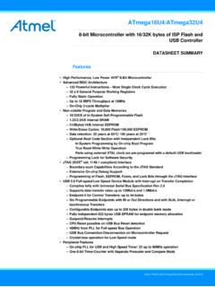
4 In case of fail, this operation is repeated with an higher timeout value (the three configurations are tested again). If the second trial fails, a system reset is Arm is a registered trademark of Arm Limited (or its subsidiaries) in the US and/or code sequenceAN31566/23AN3156 Rev 12 Figure 1. Bootloader for STM32 connectivity line devices1. After system reset, the device return to the BL_DFU loop or execute code from Flash memory/RAM, depending upon the connection states and the boot pin Leave DFU is achieved by a 0 data download request followed by GetStatus request and device After six trials (the three clock configurations are tested twice), a system reset is generated. If the product uses HSE for the USB operation (except connectivity line): At startup the HSE is measured (if present) and if it is supported the USB is configured. If the HSE is not detected the Bootloader performs a system reset. If the measured value of the HSE clock is an unsupported value, the USB protocol does not work correctly.
5 If the product uses the HSI for the USB operation: At startup the USB is configured using HSI to AN2606 for more details about product packet?No (Timeout)Ye sConfigure external oscillator mode and re-initialize USBE numeration phaseEnter DFU modeWait forHost commandsDFU requestroutinesDFU requestsJump to Leave DFUroutineLeave DFUG enerate Systemand exit DFU modeNeed reset?Reset (1) Application AddressYe sNo Mode (2)Configure internal oscillator mode and re-initialize USBUSB deviceconnectedNoYe sDevice USB resetClock detectionphase(3) Increment TrialNumTrialNum > 6 Generate SystemResetai17755AN3156 Rev 127/23AN3156 Bootloader code sequence22 Figure 2. Bootloader for other STM32 devices1. After system reset, the device returns to the BL_DFU loop or execute code from Flash memory/RAM, depending upon the connection states and the boot pin Leave DFU is achieved by a 0 data download request followed by GetStatus request and device For some products the external oscillator HSE is not used for USB bootloader operations, only the internal oscillator HSI is used.
6 Check AN2606 to know which oscillator is required for each :At bootloader startup, the internal oscillator (HSI) is used as clock source for the USB interface. When the USB event is detected, the external oscillator is configured as USB clock for enumerationNoYe sConfigure Oscillator mode(HSE/HSI)(3)Enumeration phaseEnter DFU ModeGenerate System Reset (1)Wait for Host CommandsDFU request routinesYe sNeed Reset ?Leave DFU routineJump to Application Address and exit DFU modeDFU requestsLeave DFU Mode (2)NoNoUSB DFU bootloader requestsAN31568/23AN3156 Rev 122 USB DFU bootloader requestsUSB DFU bootloader supports the DFU protocol and requests compliant with the universal serial Bus Device Upgrade Specification for Device Firmware Upgrade Version , Aug 5, 2004. For more details concerning these requests, refer to the b l e 2 and Table 3 enumerate the DFU class-specific requests and their parameters. Note:The Detach request is not meaningful in the case of the bootloader.
7 The bootloader is started by a system reset depending on the boot mode configuration settings, which means that no other Application is running at that time. Communication safetyThe communication between host and device is secured by the embedded USB protection mechanisms ( CRC checking, acknowledgments). No further protection is performed for transferred data or for bootloader specific 2. DFU class requestsRequestCodeDescriptionDFU_DETACH 0x00 Requests the device to leave DFU mode and enter the data transfer from Host to the device in order to load them into device internal Flash memory. Includes also erase data transfer from device to Host in order to load content of device internal Flash memory into a Host device to send status report to the Host (including status resulting from the last request execution and the state the device enters immediately after this request).DFU_CLRSTATUS0x04 Requests device to clear error status and move to next the device to send only the state it enters immediately after this device to exit the current state/operation and enter idle state 3.
8 Summary of DFU class-specific requests bmRequestbRequestwValuewIndexwLengthData 00100001bDFU_DETACHwTimeoutInterface ZeroNone00100001bDFU_DNLOADwBlockNumInte rface LengthFirmware10100001bDFU_UPLOADZeroInt erface LengthFirmware00100001bDFU_GETSTATUS ZeroInterface 6 Status00100001bDFU_CLRSTATUSZeroInterfac e ZeroNone00100001bDFU_GETSTATEZeroInterfa ce 1 State00100001bDFU_ABORTZeroInterface ZeroNoneAN3156 Rev 129/23AN3156 DFU bootloader commands223 DFU bootloader commandsThe DFU_DNLOAD and DFU_UPLOAD requests are mainly used to perform simple write and read memory operations. They are also used to initiate the integrated bootloader commands (such as Write, Read Unprotect, Erase, Set Address). The DFU_GETSTATUS command then triggers the command the DFU download request the command is selected through the wValue parameter in the USB request structure. If wValue = 0 then the data sent by the host after the request is a bootloader command code.
9 The first byte is the command code and the other bytes (if any) are the data related to this the DFU upload request the command is selected through the wValue parameter in the USB request structure. If wValue = 0 then Get Command is selected and performed. If the user performs a Read Unprotect operation while the memory is not protected, the whole RAM is cleared by the bootloader firmware and the Flash memory is not erased (since it was not previously read-protected).There are no commands for the Write Protect, Write Unprotect and Read Protect operations. These operations can be performed through the Write Memory and Read Memory commands used for the option byte 4. DFU bootloader commands DFU requestBootloader commandWrite protection disabledRead protection disabledWrite protection enabledRead protection disabledRead protection enabledDFU_UPLOADRead MemoryAllowedAllowedNot allowedGetAllowedAllowedAllowedDFU_DNLOA DW rite MemoryAllowedAllowed(1)1.
10 This operation is allowed but not effective: the bootloader does not return an error but the operation is not executed since the sectors are write-protected. This applies only to the Flash memory. It does not apply to the RAM or to the option byte allowedEraseAllowedAllowed(1)Not allowedRead UnprotectN/A(2)2. Not applicable (this operation is allowed but has no meaning since the memory is not protected).N/A(2)Allowed(3)3. In this case, both the Flash memory (from 0x0800 0000) and the RAM are erased. The option byte area is reset to default Address PointerAllowedAllowedAllowedLeave DFU modeAllowedAllowedAllowedDFU_UPLOAD request commandsAN315610/23AN3156 Rev 124 DFU_UPLOAD request commandsThe upload request enables the execution of different commands, their selection is done through the value of parameter wValue in the USB request structure. The supported operations are described in Sections to Read memoryThe Read memory operation is selected when wValue > host requests the device to send a specified number of data bytes (wLength) from valid memory address (see note) of the internal Flash memory, embedded RAM, system memory or from the option :Refer to Section 4 for more details about the valid memory addresses for the used allowed number of bytes to read depends on the memory target: for the internal Flash memory, embedded RAM and system memory read size can be from 2 to 2048 bytes for the option bytes read size has to be equal to the option byte block size for other memory locations, refer to address from which the host requests to read data is computed using the value of wBlockNumber (wValue) and the address pointer according to the following formula:Address = ((wBlockNum 2) wTransferSize) + Address_Pointer, where.