Transcription of ATLANTA Rack & Pinion Mounting Guidelines
1 73 Mounting of Rack & Pinion DrivesMounting Guidelines of Rack & PinionsRacks can be mounted in any position. In environments wheredebris (sawdust, etc.) is present, the rack should be mountedwith the teeth facing down or covered to minimize contami-nation. Racks are typically mounted on their side faces dueto the Mounting hole locations; Mounting holes can be drilledin the back face if necessary. It is recommended that a smallright-angle ledge be provided on the Mounting surface tolocate the rack on two faces. This makes it easier to accu-rately mount several pieces of rack in Mounting and alignment of rack & Pinion drives is criticalto the performance and lifetime of the axis.
2 The following in-structions are meant to be general Guidelines on how toachieve an accurate Mounting of a rack & Pinion Mount and align the linear slides (rails) to the axis the location of the rail in relation to the rack mount-ing surface with a dial indicator. A shoulder should be pro-vided on the Mounting surface to locate the back of therack. The rack Mounting surface tolerance will affect thecontact pattern of the drive; the rack shoulder tolerancewill affect the backlash of the drive. The more accuratethese surfaces are, the better the axis will Attach the first rack segment to the rack Mounting sur-face. The Mounting holes in the rack require hex-socketcap screws, which should be tightened to 7 for theM6 and 15 for the M8.
3 Measure the location of the railin relation to the pitchline of the rack segment with a dialindicator. To locate the pitchline of the rack, a pin is placedin-between the rack teeth and an over-pin tolerance is mea-sured:If the tolerances are found to be high, the rack should beshimmed accordingly and the rack Mounting surface andshoulder should be checked Attach the next rack segment to the rack Mounting sur-face. A companion rack should be used to properly spacethe gap in-between helical rack segments; a meterpiece of rack should be used in-between straight rack seg-ments (see diagram). Again measure the location from therail in relation to the rack segment.
4 Continue Mounting therack segments for the entire travel length using the Mount the Pinion to the rail carriage. Make sure the pinionengages the total face width of the rack. Check of the align-ment of the rack & Pinion by marking or bluing the pinionteeth with a high spot paste (Dykem) and slowly runningthe axis in both directions. This will show the tooth contactpattern between the rack a contact pattern acrossthe majority of the tooth flank on both the rack and pinionis desired. If the contact pattern is shifted to one side ofthe tooth flanks, some form of misalignment is Measure the linear backlash between the rack & pinionalong the entire axis travel length.
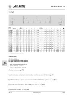
5 The minimum backlashusing a hardened & ground Pinion should be as follows:Companion rack for assemblyRack 1If the backlash is found to be less in any location along thetravel length, the Pinion should be pulled away from therack (increasing the center distance). If it is found to bemore, the Pinion location could be left as is or moved closerto the rack (decreasing the center distance) if needed forthe desired accuracy of the Run the axis through the entire rack travel length to checkfor any problems, such as binding or excessive noise. Ifeither is found, the alignment of the axis must be checkedagain. Finally, drill dowel pin holes into the rack mountingsurface using the starter holes in racks.
6 Place dowel pinsin the holes (two for each rack segment).Guide bushing for round racksThe guide bushings are practically maintenance free and thussuitable for normal, low-stress service. It may be necessaryto provide a lubricant reservoir, by Mounting two collar bush-ings with a gap in-between them. If high loads and/or axialmovement are expected, please consult us. The bore in thehousing should be manufactured to H7 tolerance. After press-ing in (with pin tolerance m5), a tolerance range of H7 can beexpected inside the instructionsThe following preventive measures are necessary: Ensurethere is no contact with rotating elements (output shaft, gears,rack, etc) and the gearbox Mounting screws are tight.
7 Avoidcontact with lubricants, refer to safety data Size SizeModule Size Rack QualityMinimum BacklashInduction mm ( )Quenched & mm ( )Hardened & mm ( )Rack 1