Transcription of CHAPTER 1: THE OP AMP - Analog Devices
1 THE OP AMP CHAPTER 1: THE OP AMP INTRODUCTION SECTION : OP AMP OPERATION INTRODUCTION VOLTAGE FEEDBACK (VFB) MODEL BASIC OPERATION INVERTING AND NONINVERTING CONFIGURATIONS OPEN-LOOP GAIN GAIN BANDWIDTH PRODUCT STABILITY CRITERIA PHASE MARGIN CLOSED-LOOP GAIN SIGNAL GAIN NOISE GAIN LOOP GAIN BODE PLOT CURRENT FEEDBACK (CFB)
2 MODEL DIFFERENCES FROM VFB HOW TO CHOOSE BETWEEN VFB AND CFB SUPPLY VOLTAGES SINGLE-SUPPLY CONSIDERATIONS CIRCUIT DESIGN CONSIDERATIONS FOR SINGLE- SUPPLY SYSTEMS RAIL-TO-RAIL PHASE REVERSAL LOW POWER AND MICROPOWER PROCESSES EFFECTS OF OVERDRIVE ON OP AMP INPUTS SECTION : OP AMP SPECIFICATIONS INTRODUCTION DC SPECIFICATIONS OPEN-LOOP GAIN OPEN-LOOP TRANSRESISTANCE OF A CFB OP AMP OFFSET VOLTAGE OFFSET VOLTAGE DRIFT DRIFT WITH TIME SECTION : OP AMP SPECIFICATIONS (cont.)
3 CORRECTION FOR OFFSET VOLTAGE DigiTrim TECHNOLOGY EXTERNAL TRIM INPUT BIAS CURRENT INPUT OFFSET CURRENT COMPENSATING FOR BIAS CURRENT CALCULATING TOTAL OUTPUT OFFSET ERROR DUE TO IB AND VOS BASIC LINEAR DESIGN INPUT IMPEDANCE INPUT CAPACITANCE INPUT COMMON MODE VOLTAGE RANGE DIFFERENTIAL INPUT VOLTAGE SUPPLY VOLTAGES QUIESCENT CURRENT OUTPUT VOLTAGE SWING (OUTPUT VOLTAGE HIGH / OUTPUT VOLTAGE LOW) OUTPUT CURRENT (SHORT-CIRCUIT CURRENT) AC SPECIFICATIONS NOISE VOLTAGE NOISE NOISE BANDWIDTH NOISE FIGURE CURRENT NOISE TOTAL NOISE (SUM OF NOISE SOURCES) 1/f NOISE (FLICKER NOISE) POPCORN NOISE RMS NOISE CONSIDERATIONS TOTAL OUTPUT NOISE CALCULATIONS DISTORTION THD (TOTAL HARMONIC DISTORTION) THD + N (TOTAL HARMONIC DISTORTION PLUS NOISE) INTERMODULATION DISTORTION THIRD+C65 ORDER INTERCEPT POINT (IP3), SECOND ORDER C56 INTERCEPT POINT (IP2) 1 dB COMPRESSION POINT SNR (SIGNAL TO NOISE RATIO)
4 ENOB (EQUIVALENT NUMBER OF BITS) OP AMP SPECIFICATIONS (cont.) SPURIOUS-FREE DYNAMIC RANGE (SFDR) SLEW RATE FULL POWER BANDWIDTH 3 dB SMALL SIGNAL BANDWIDTH BANDWIDTH FOR dB BANDWIDTH FLATNESS+C65 GAIN-BANDWIDTH PRODUCT CFB FREQUENCY DEPENDANCE SETTLING TIME RISE TIME AND FALL TIME PHASE MARGIN CMRR (COMMON-MODE REJECTION RATIO) PSRR (POWER SUPPLY REJECTION RATIO) DIFFERENTIAL GAIN DIFFERENTIAL PHASE PHASE REVERSAL CHANNEL SEPARATION ABSOLUTE MAXIMUM RATING REFERENCES THE OP AMP SECTION : HOW TO READ DATA SHEETS THE FRONT PAGE THE SPECIFICATION TABLES THE ABSOLUTE MAXIMUMS THE ORDERING GUIDE THE GRAPHS THE MAIN BODY SECTION : CHOOSING AN OP AMP STEP 1: DETERMINE THE PARAMETERS STEP 2: SELECTING THE PART BASIC LINEAR DESIGN THE OP AMP INTRODUCTION CHAPTER 1.
5 THE OP AMP Introduction In this CHAPTER we will discuss the basic operation of the op amp, one of the most common linear design building blocks. In section 1 the basic operation of the op amp will be discussed. We will concentrate on the op amp from the black box point of view. There are a good many texts that describe the internal workings of an op amp, so in this work a more macro view will be taken. There are a couple of times, however, that we will talk about the insides of the op amp. It is unavoidable. In section 2 the basic specifications will be discussed. Some techniques to compensate for some of the op amps limitations will also be given. Section 3 will discuss how to read a data sheet. The various sections of the data sheet and how to interpret what is written will be discussed. Section 4 will discuss how to select an op amp for a given application.
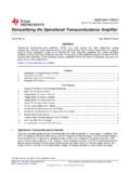
6 BASIC LINEAR DESIGN THE OP AMP OP AMP OPERATION SECTION 1: OP AMP OPERATION Introduction The op amp is one of the basic building blocks of linear design. In its classic form it consists of two input terminals, one of which inverts the phase of the signal, the other preserves the phase, and an output terminal. The standard symbol for the op amp is given in Figure This ignores the power supply terminals, which are obviously required for operation. Figure : Standard op amp symbol The name op amp is the standard abbreviation for operational amplifier . This name comes from the early days of amplifier design, when the op amp was used in Analog computers. (Yes, the first computers were Analog in nature, rather than digital). When the basic amplifier was used with a few external components, various mathematical operations could be performed.
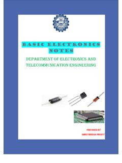
7 One of the primary uses of Analog computers was during WWII, when they were used for plotting ordinance trajectories. Voltage Feedback (VFB) Model The classic model of the voltage feedback op amp incorporates the following characteristics: 1.) Infinite input impedance 2) Infinite bandwidth 3) Infinite gain 4) Zero output impedance 5) Zero power consumption INPUTS(+)(-)INPUTS(+)(-) BASIC LINEAR DESIGN None of these can be actually realized, of course. How close we come to these ideals determines the quality of the op amp. This is referred to as the voltage feedback model. This type of op amp comprises nearly all op amps below 10 MHz bandwidth and on the order of 90% of those with higher bandwidths. Figure : The Attributes of an Ideal Op Amp Basic Operation The basic operation of the op amp can be easily summarized.
8 First we assume that there is a portion of the output that is fed back to the inverting terminal to establish the fixed gain for the amplifier . This is negative feedback. Any differential voltage across the input IDEAL OP AMP ATTRIBUTES Infinite Differential Gain Zero Common Mode Gain Zero Offset Voltage Zero Bias Current Infinite Bandwidth OP AMP INPUT ATTRIBUTES Infinite Impedance Zero Bias Current RespondtoDifferentialVoltages Do Not Respond to Common Mode Voltages OP AMP OUTPUT ATTRIBITES Zero ImpedanceOP AMPOUTPUTPOSITIVESUPPLYNEGATIVE SUPPLYINPUTS(+)(-)OP AMPOUTPUTPOSITIVESUPPLYNEGATIVE SUPPLYINPUTS(+)(-)THE OP AMP OP AMP OPERATION terminals of the op amp is multiplied by the amplifier s open-loop gain. If the magnitude of this differential voltage is more positive on the inverting (-) terminal than on the noninverting (+) terminal, the output will go more negative.
9 If the magnitude of the differential voltage is more positive on the noninverting (+) terminal than on the inverting (-) terminal, the output voltage will become more positive. The open-loop gain of the amplifier will attempt to force the differential voltage to zero. As long as the input and output stays in the operational range of the amplifier , it will keep the differential voltage at zero, and the output will be the input voltage multiplied by the gain set by the feedback. Note from this that the inputs respond to differential mode not common-mode input voltage. Inverting and Noninverting Configurations There are two basic ways to configure the voltage feedback op amp as an amplifier . These are shown in Figure and Figure Figure shows what is known as the inverting configuration.
10 With this circuit, the output is out of phase with the input. The gain of this circuit is determined by the ratio of the resistors used and is given by: Figure : Inverting Mode Op Amp Stage Eq. 1-1 VIN= - RF/RGVOUTOP AMPRFRGG = VOUT/VINSUMMING POINTA = -RfbRinRfbRinRfbRinRfbRinA = -RfbRinRfbRinRfbRinRfbRinA = -RfbRinRfbRinRfbRinRfbRin BASIC LINEAR DESIGN Figure shows what is know as the noninverting configuration. With this circuit the output is in phase with the input. The gain of the circuit is also determined by the ratio of the resistors used and is given by: Figure : Noninverting Mode Op Amp Stage Note that since the output drives a voltage divider (the gain setting network) the maximum voltage available at the inverting terminal is the full output voltage, which yields a minimum gain of 1.