Transcription of CHAPTER 10: PASSIVE COMPONENTS - Analog Devices
1 PASSIVE COMPONENTS CHAPTER 10: PASSIVE COMPONENTS INTRODUCTION SECTION : CAPACITORS BASICS DIELECTRIC types TOLERANCE, TEMPERATURE, AND OTHER EFFECTS PARASITICS DIELLECTRIC ABSORPTION CAPACITOR PARASITICS AND DISSIPATION FACTOR ASSEMBLE CRITICAL COMPONENTS LAST SECTION.
2 RESISTORS AND POTENTIOMETERS BASICS RESISTOR PARASITICS THERMOELECTRIC EFFECTS VOLTAGE SENSITIVITY, FAILURE MECHANISMS, AND AGING RESISTOR EXCESS NOISE POTENTIOMETERS SECTION : INDUCTORS BASICS FERRITES REFERENCES
3 BASIC LINEAR DESIGN PASSIVE COMPONENTS INTRODUCTION CHAPTER 10: PASSIVE COMPONENTS Introduction When designing precision Analog circuits, it is critical that users avoid the pitfall of poor PASSIVE component choice. In fact, the wrong PASSIVE component can derail even the best op amp or data converter application. This section includes discussion of some basic traps of choosing PASSIVE COMPONENTS . So, you've spent good money for a precision op amp or data converter, only to find that, when plugged into your board, the device doesn't meet spec. Perhaps the circuit suffers from drift, poor frequency response, and oscillations or simply doesn't achieve expected accuracy.
4 Well, before you blame the device, you should closely examine your PASSIVE COMPONENTS including capacitors, resistors, potentiometers, and yes, even the printed circuit boards. In these areas, subtle effects of tolerance, temperature, parasitics, aging, and user assembly procedures can unwittingly sink your circuit. And all too often these effects go unspecified (or underspecified) by PASSIVE component manufacturers. In general, if you use data converters having 12 bits or more of resolution, or high precision op amps, pay very close attention to PASSIVE COMPONENTS . Consider the case of a 12-bit DAC, where LSB corresponds to of full scale, or only 122 ppm.
5 A host of PASSIVE component phenomena can accumulate errors far exceeding this! But, buying the most expensive PASSIVE COMPONENTS won't necessarily solve your problems either. Often, a correct 25-cent capacitor yields a better-performing, more cost-effective design than a premium-grade (expensive) part. With a few basics, understanding and analyzing PASSIVE COMPONENTS may prove rewarding, albeit not easy. BASIC LINEAR DESIGN Notes: PASSIVE COMPONENTS CAPACITORS SECTION : CAPACITORS Basics A capacitor is a PASSIVE electronic component that stores energy in the form of an electrostatic field. In its simplest form, a capacitor consists of two conducting plates separated by an insulating material called the dielectric.
6 The capacitance is directly proportional to the surface areas of the plates, and is inversely proportional to the separation between the plates. Capacitance also depends on the dielectric constant of the substance separating the plates. Capacitive reactance is defined as: XC = 1/ C = 1/2 fC where XC is the capacitive reactance, is the angular frequency, f is the frequency in Hertz, and C is the capacitance. Capacitive reactance is the negative imaginary component of impedance. The complex impedance of an inductor is then given by: Z =1/ j C = 1/j2 fC where j is the imaginary number. Dielectric types There are many different types of capacitors, and an understanding of their individual characteristics is absolutely mandatory to the design of practical circuits.
7 A thumbnail sketch of capacitor characteristics is shown in the chart of Figure Background and tutorial information on capacitors can be found in Reference 2 and many vendor catalogs. With any dielectric, a major potential filter loss element is ESR (equivalent series resistance), the net parasitic resistance of the capacitor. ESR provides an ultimate limit to filter performance, and requires more than casual consideration, because it can vary both with frequency and temperature in some types . Another capacitor loss element is ESL (equivalent series inductance). ESL determines the frequency where the net impedance of the capacitor switches from a capacitive to inductive characteristic.
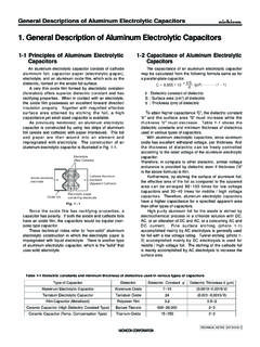
8 This varies from as low as 10 kHz in some electrolytics to as high as 100 MHz or more in chip ceramic types . Both ESR and ESL are minimized when a leadless package is used, and all capacitor types discussed here are available in surface mount packages, which are preferable for high speed uses. j= -1j= -1Eq. 10-1 Eq. 10-2 Eq. 10-3 BASIC LINEAR DESIGN The electrolytic family provides an excellent, cost effective low-frequency filter component , because of the wide range of values, a high capacitance-to-volume ratio, and a broad range of working voltages. It includes general-purpose aluminum electrolytic types , available in working voltages from below 10 V up to about 500 V, and in size from 1 F to several thousand F (with proportional case sizes).
9 All electrolytic capacitors are polarized, and thus cannot withstand more than a volt or so of reverse bias without damage. They have relatively high leakage currents (this can be tens of A, but is strongly dependent upon specific family design, electrical size and voltage rating versus applied voltage). However, this is not likely to be a major factor for basic filtering applications. Also included in the electrolytic family are tantalum types , which are generally limited to voltages of 100 V or less, with capacitance of 500 F or less. In a given size, tantalums exhibit higher capacitance-to-volume ratios than do the general purpose electrolytics, and have both a higher frequency range and lower ESR.
10 They are generally more expensive than standard electrolytics, and must be carefully applied with respect to surge and ripple currents. A subset of aluminum electrolytic capacitors is the switching type, which is designed and specified for handling high pulse currents at frequencies up to several hundred kHz with low losses. This type of capacitor competes directly with the tantalum type in high frequency filtering applications, and has the advantage of a much broader range of available values. More recently, high performance aluminum electrolytic capacitors using an organic semiconductor electrolyte have appeared.