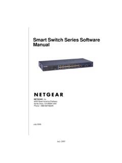
Transcription of D-Link Web Smart Switch User Manual
1 D-Link Web Smart Switch User Manual Table of Contents Table of Contents .. i About This 1. 1. Copyright and Trademarks .. 1. Product Introduction .. 2. DES-1100-16 .. 2. Front Panel .. 2. Rear 2. DES-1100-24 .. 2. Front Panel .. 2. Rear 3. Hardware Installation .. 4. Step 1: 4. Step 2: Switch 4. Desktop or Shelf 4. Rack Installation .. 4. Step 3 Plugging in the AC Power 6. Power Failure .. 6. Grounding the Switch .. 6. Getting 7. Management 7. Using Web-based Management .. 7. Supported Web Browsers .. 7. Connecting to the 7. Login Web-based Management .. 8. SmartConsole 8. SmartConsole Utility .. 10. SmartConsole Settings .. 10. Utility 10. 11. Trap .. 11. File .. 12. Help .. 12. Device 13. Add(+), Delete(-) and Discover the device .. 15. Device 16. Configuration .. 18. Web-based 18.
2 Tool Bar > Save Menu .. 19. Save Configuration .. 19. Tool Bar > Tool Menu .. 19. Reset System .. 19. Reboot Device .. 19. Firmware 19. Configuration Backup & Restore .. 20. Function Tree .. 21. Device 21. i D-Link Web Smart Switch User Manual System > System Settings .. 22. System > Port 23. System > Trap Settings For 23. System > Password Access Control .. 24. L2 Features > Port 24. L2 Features > IGMP 24. L2 Features > Port Mirroring .. 25. L2 Features > Loopback Detection .. 25. L2 Features > 26. VLAN > 28. VLAN > Port-Base 30. QoS > Default 31. QoS > Storm Control .. 31. QoS > Bandwidth 32. Security > MAC Address Table > Static 33. Security > MAC Address Table > Dynamic Forwarding 33. Appendix A - Ethernet 35. Gigabit Ethernet Technology .. 35. Fast Ethernet 35. Switching Technology.
3 35. Appendix B - Technical Specifications .. 62. Hardware Specifications .. 62. Key Components / Performance .. 62. Port Functions .. 62. Physical & Environment .. 62. Emission (EMI) Certifications .. 62. Safety 62. Features .. 62. L2 Features .. 62. VLAN .. 62. QoS (Quality of Service).. 62. 62. Appendix C Rack mount Instructions .. 63. ii D-Link Web Smart Switch User Manual About This Guide This guide provides instructions to install the D-Link Fast Ethernet EasySmart Switch DES-1100-16/24, how to use the Web Utility, and to configure Web-based Management step-by-step. Note: The model you have purchased may appear slightly different from the illustrations shown in the document. Refer to the Product Instruction and Technical Specification sections for detailed information about your Switch , its components, network connections, and technical specifications.
4 This guide is mainly divided into four parts: 1. Hardware Installation: Step-by-step hardware installation procedures. 2. Getting Started: A startup guide for basic Switch installation and settings. 3. Smart Console Utility: An introduction to the central management system. 4. Configuration: Information about the function descriptions and configuration settings. Terms/Usage In this guide, the term Switch (first letter capitalized) refers to the EasySmart Switch , and Switch (first letter lower case) refers to other Ethernet switches. Some technologies refer to terms Switch , bridge and switching hubs interchangeably, and both are commonly accepted for Ethernet switches. A NOTE indicates important information that helps a better use of the device. A CAUTION indicates potential property damage or personal injury.
5 Copyright and Trademarks Information in this document is subjected to change without notice. 2010 D-Link Corporation. All rights reserved. Reproduction in any manner whatsoever without the written permission of D-Link Corporation is strictly forbidden. Trademarks used in this text: D-Link and the D-Link logo are trademarks of D-Link Corporation; Microsoft and Windows are registered trademarks of Microsoft Corporation. Other trademarks and trade names may be used in this document to refer to either the entities claiming the marks and names or their products. D-Link Corporation disclaims any proprietary interest in trademarks and trade names other than its own. 1. D-Link Web Smart Switch User Manual 1 Product Introduction Thank you and congratulations on your purchase of D-Link EasySmart Switch Products.
6 D-Link 's next generation EasySmart Ethernet Switch series blends plug-and-play simplicity with exceptional value and reliability for small and medium-sized business (SMB) networking. All models are housed in a new style rack-mount metal case with easy-to-view front panel diagnostic LEDs. DES-1100-16. 16-Port 10/100 Mpbs EasySmart Switch Front Panel Figure 1 DES-1100-16 Front Panel Power LED: The Power LED lights up when the Switch is connected to a power source. Link/Act/Speed LED (Ports 1-16): Flashing: Indicates a network link through the corresponding port. Blinking: Indicates that the Switch is either sending or receiving data to the port. Green: Indicates that the port is running at 100M. Light off: Indicates that the port is running at 10M. Reset: By pressing the Reset button the Switch will change back to the default configuration and all changes will be lost.
7 Rear Panel Figure 2 DES-1100-16 Rear Panel Power: The power port is where to connect the AC power cord. DES-1100-24. 24-Port 10/100 Mpbs EasySmart Switch Front Panel Figure 3 DES-1100-24 Front Panel 2. D-Link Web Smart Switch User Manual Power LED: The Power LED lights up when the Switch is connected to a power source. Link/Act/Speed LED (Ports 1-24): Flashing: Indicates a network link through the corresponding port. Blinking: Indicates that the Switch is either sending or receiving data to the port. Green: Indicates that the port is running at 100M. Light off: Indicates that the port is running at 10M. Reset: Press the reset button to reset the Switch back to the default settings. All previous changes will be lost. Rear Panel Figure 4 DES-1100-24 Rear Panel Power: Connect the supplied AC power cable to this port.
8 3. D-Link Web Smart Switch User Manual 2 Hardware Installation This chapter provides unpacking and installation information for the D-Link EasySmart Switch . Step 1: Unpacking Open the shipping carton and carefully unpack its contents. Please consult the packing list located in the User Manual to make sure all items are present and undamaged. If any item is missing or damaged, please contact your local D-Link reseller for replacement. One D-Link EasySmart Switch One AC power cord Four rubber feet Screws and two mounting brackets One accessory kit for a ground screw One Multi-lingual Getting Started Guide One CD with User Manual and SmartConsole Utility program If any item is found missing or damaged, please contact the local reseller for replacement. Step 2: Switch Installation For safe Switch installation and operation, it is recommended that you: Visually inspect the power cord to see that it is secured fully to the AC power connector.
9 Make sure that there is proper heat dissipation and adequate ventilation around the Switch . Do not place heavy objects on the Switch . Desktop or Shelf Installation When installing the Switch on a desktop or shelf, the rubber feet included with the device must be attached on the bottom at each corner of the device's base. Allow enough ventilation space between the device and the objects around it. Figure 5 Attach the adhesive rubber pads to the bottom Rack Installation The Switch can be mounted in an EIA standard size 11-inch rack, which can be placed in a wiring closet with other equipment. To install, attach the mounting brackets to the Switch 's side panels (one on each side) and secure them with the screws provided (please note that these brackets are not designed for palm size switches).
10 4. D-Link Web Smart Switch User Manual Figure 6 Attach the mounting brackets to the Switch Then, use the screws provided with the equipment rack to mount the Switch in the rack. Figure 7 Mount the Switch in the rack or chassis Please be aware of following safety Instructions when installing: A) Elevated Operating Ambient - If installed in a closed or multi-unit rack assembly, the operating ambient temperature of the rack environment may be greater than room ambient. Therefore, consideration should be given to installing the equipment in an environment compatible with the maximum ambient temperature (Tma). specified by the manufacturer. B) Reduced Air Flow - Installation of the equipment in a rack should be such that the amount of air flow required for safe operation of the equipment is not compromised.