Example: quiz answers
Debugger Basics - Training
Basic TRACE32 PowerView Parameters This chapter describes the basic parameters required to start a TRACE32 PowerView instance. The parameters are defined in the configuration file. By default the configuration file is named config.t32. It is located in the TRACE32 system directory (parameter SYS). Configuration File
Tags:
Information
Domain:
Source:
Link to this page:
Documents from same domain
Debugger Basics - Training - Lauterbach
www2.lauterbach.comDebugger Basics - Training 6 ©1989-2018 Lauterbach GmbH On-chip Debug Interface The TRACE32 debugger allows you to test your …
General Commands Reference Guide D - Lauterbach
www2.lauterbach.comGeneral Commands Reference Guide D 1 ©1989-2018 Lauterbach GmbH General Commands Reference Guide D TRACE32 Online Help TRACE32 Directory

Training JTAG Interface - Lauterbach
www2.lauterbach.comTraining JTAG Interface 1 ©1989-2018 Lauterbach GmbH Training JTAG Interface TRACE32 Online Help TRACE32 Directory TRACE32 Index

PRACTICE Script Language User's Guide - Lauterbach
www2.lauterbach.comPRACTICE Script Language User’s Guide 3 ©1989-2018 Lauterbach GmbH Why Use PRACTICE Scripts Using PRACTICE scripts (*.cmm) in TRACE32 will help you to:

ARM Debugger - Lauterbach
www2.lauterbach.comARM Debugger 1 ©1989-2018 Lauterbach GmbH ARM Debugger TRACE32 Online Help TRACE32 Directory TRACE32 Index TRACE32 Documents .....
TriCore Debugger and Trace
www2.lauterbach.comTriCore Debugger and Trace 1 ©1989-2018 Lauterbach GmbH TriCore Debugger and Trace TRACE32 Online Help TRACE32 Directory TRACE32 Index
eMMC FLASH Programming User's Guide - …
www2.lauterbach.comeMMC FLASH Programming User’s Guide 13 ©1989-2018 Lauterbach GmbH The following framework can be used as base for eMMC Flash programming:

Training Linux Debugging - Lauterbach
www2.lauterbach.comTraining Linux Debugging 2 ©1989-2018 Lauterbach GmbH Boot Linux 32 3.) Example Linux Setup-Scripts 33 Debugging the Linux Components ..... 36

IDE Functions
www2.lauterbach.comIDE Functions 1 ©1989-2018 Lauterbach GmbH IDE Functions TRACE32 Online Help TRACE32 Directory TRACE32 Index TRACE32 Documents .....
TRACE32 Installation Guide
www2.lauterbach.comTRACE32 Installation Guide 8 ©1989-2018 Lauterbach GmbH TRACE32-ICD (In-Circuit Debugging) Host-based Interfaces This chapter describes the host-based USB and Ethernet configurations.
Related documents

PACIFIC GAS AND ELECTRIC COMPANY BASIC WAGE …
ibew1245.com50444050 0821 Cable Crew Foreman (+7 Emps) $ 63.54 $ 65.45 50072918 1105 Cable Lineman - Temporary $ 54.70 $ 56.34 50010375 2280 Cable Splicer $ 56.63 $ 58.33 50010380 2286 Unassigned Cable Splicer 50010091 0140 Cableman - San Francisco Division Start $ 59.61 $ …
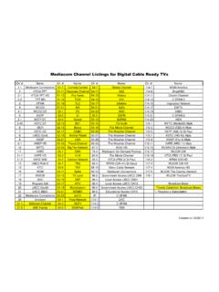
Mediacom Channel Listings for Digital Cable Ready TVs
www.lmcc-tv.orgDec 22, 2011 · 19 Wayzata Sch 53-17 MTV 96-4 Local Access LMCC CH12 Broadcast Basic 20 LMCC Gov20 53-19 Nickelodeon 96-5 Government Access LMCC CH20 *Family Cable(Incl. Broadcast Basic) 21 LMCC BB21 53-21 MSNBC 96-6 Educational Access CH19 *= Requires a Subscription 22 Mediacom Connections 53-23 truTV 97 C-SPAN 23 Univision 54-1 Food …

Lab: Basic Router Configuration
courses.cs.ut.eeTask 1: Cable the Network. Cable a network that is similar to the one in the Topology Diagram. The output used in this lab is from 1841 routers. You can use any current router in your lab as long as it has the required interfaces as shown in the topology. Be sure to use the appropriate type of Ethernet cable to connect from host to

Instrument Transformer Basic Technical Information and ...
www.gegridsolutions.comthe primary cable through the window of the CT. An example would be the need for a 100 ampere to 5 unit when the lowest current rating made by the manufacturer was 200 to 5 amperes. By looping the cable through the window so that the cable passes through the window twice, we can make an effective 100:5 ampere unit out of a 200:5 ampere unit.

The Atmel-ICE Debugger - Microchip Technology
ww1.microchip.comTwo cable options are provided in the full kit: • 50-mil 10-pin IDC flat cable with 6-pin ISP and 10-pin connectors • 50-mil 10-pin mini-squid cable with 10 x 100-mil sockets Figure 2-7. Atmel-ICE Cables For most purposes, the 50-mil 10-pin IDC flat cable can be used, connecting either natively to its 10-pin

Basic Antenna Theory
wireless.ictp.itBasic Antenna Theory Ryszard Struzak Note: These are preliminary notes, intended only for distribution among the participants. Beware of misprints! ... • The center conductor of the feeding coaxial cable is connected to one side of the slot, and the outside conductor of the cable - to the other side of the slot. ...

Power Cable Splicing and Terminating Guide
media.distributordatasolutions.compractice to cut off a portion of cable after pulling to assure an undamaged end. A key to good cable preparation is the use of sharp, high quality tools. When the various layers are removed, cuts should extend only partially through the layer. For example, when removing cable insulation, the installer

Basic jumper settings for Western Digital ATA Hard Drives
eshop.macsales.comBasic jumper settings for Western Digital ATA Hard Drives ... If your existing drive is set for “Cable Select”, then set your new drive to “Cable Select” also. You can change the existing jumper settings on the original drive to suit your needs, but we recommend following these instructions fi rst to verify proper ...

Basic Schematic Interpretation
www.freeinfosociety.comadjacent electrical influence. The shielding on the cable may or may not be grounded. Figure 1-2 shows some common symbols for shielded conductors. Figure 1-2. Shielded Conductors. 3. Basic Components. There are literally hundreds of different types of electrical and electronic components in use today. However,

Basic Course Workbook Series - California
post.ca.govThis student workbook is part of the POST Basic Course Training System. The workbook component of this system provides a self-study document for every learning domain in the Basic Course. Each workbook is intended to be a supplement to, not …