Transcription of Demystifying the Operational Transconductance Amplifier ...
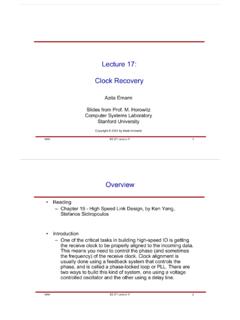
1 1 SBOA117A May 2009 RevisedApril2013 SubmitDocumentationFeedbackCopyright 2009 2013,TexasInstrumentsIncorporatedDemysti fyingthe OperationalTransconductanceAmplifierAll trademarksare the propertyof May 2009 RevisedApril2013 Demystifyingthe (OTAs) ,thesedevicesservea veryusefulfunctionthat is beingimplementedon a regularbasisin manyintegratedcircuitsas an elementfor moreadvancedpurposes;the currentfeedbackamplifieris amongthe purposeof this applicationreportis to showhow also developsseveralexamplesof how this typeof componentcan be put togooduse for of an of Figures1 TypicalOTAE lementsand the (CC Type2) with the the versatilebuildingblocksthat intrinsicallyofferwidebandwidthfor manytypesof ,or voltage-controlledcurrentsource,can be viewedas an the transistormodel,ithas threeterminals:a high inputimpedance(base,orB); a low-impedanceinput/output(emitter,orE);a nd a currentoutput(collector,orC).
2 However,unlikea bipolartransistor,the OTAis self-biasedand hasbipolaroutput,meaningthat the outputcurrentsourcecan eithersourceor sink the zerofor a zeroproducean output3 B2EC8 OPA861VI100 WRERLVON oninverting GainV= 0 VOST ransconductor(used here)CBED iamondTransistor321 VIN2 IOUTVIN1 Voltage-ControlledCurrent SourceIOUTVIN2 VIN1 ZCCII+ current Conveyor II+CBEM acro May 2009 RevisedApril2013 SubmitDocumentationFeedbackCopyright 2009 2013,TexasInstrumentsIncorporatedDemysti fyingthe OperationalTransconductanceAmplifiercurr entthat is bipolarand also centeredon transconductanceelementis traditionallyadjustablewith an externalresistance,allowingtrade-offsin bandwidth,quiescentcurrent,and a basicbuildingblock,an OTAelementsimplifiesdesignsof automaticgain control(AGC)amplifiers,light-emittingdio de(LED)drivercircuits,fast-pulseintegrat ors,controlloopsfor capacitivesensors,and activefilters,aswell as yearsand dependingon the writer,an OTAhas beenreferredto as adiamondtransistor, avoltage-controlledcurrentsource, atransconductor, amacrotransistor, and apositivesecond-generationcurrentconveyo ror CCII+.
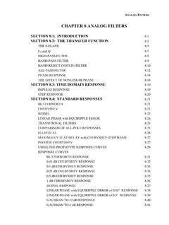
3 Figure1 illustratesthesetermsand the correspondingsymbolsgenerallyusedto TypicalOTAE lementsand AcceptedReferencesRegardlessof how it is illustratedor defined,the OTAhas a high impedanceterminal(B); a lowimpedanceterminal(E) that can be consideredeitheras an inputor an outputdependingon the circuit;and a outputcurrentsourceterminal(C). The outputcurrentsourceterminalis high the transconductor,any voltagethat appearsbetweenB and E will generatea currentthat flowsout ofC. For the balanceof this document,however,we will first circuitthat demonstrateshow an OTAoperatesis shownin BasicOTAC ircuitArchitectureLookingat the internalarchitectureof the OTAas shownin Figure2, a bufferis presentbetweenthe B-inputand the bufferplacesa copyof the inputvoltageto the voltagepresenton the E-outputgeneratesa currentthroughthe currentflowingout of the REresistoristhenduplicatedand flowsout of the currentis convertedbackto a voltageby passingthroughthe load total gain for the circuitillustratedin Figure2 is set by RL/RE.
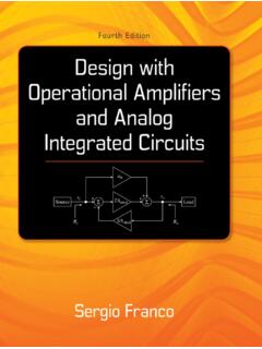
4 The inputishigh impedanceand the outputimpedanceis set by the load a 100 resistanceisplacedin serieswith the resistancehelpsisolatethe parasiticinputcapacitanceof the OTAfromthe earliervoltage-modestageto help valuerangingfrom25 to 100 is a current -modestageis used,this seriesresistoris not + RE1gmg=m_degR+ RLE1gmG =3 B2EC8 OPA861VI100 WRERLVON oninverting GainV= May 2009 RevisedApril2013 SubmitDocumentationFeedbackCopyright 2009 2013,TexasInstrumentsIncorporatedDemysti fyingthe includean OTA: OPA860(an OTAand a closed-loopbuffer) OPA861(an OTA) OPA615(a wide-bandwidthdc restorationcircuitthat containsan OTAand a switchingOTA,or SOTA)Informationon theseproductsis availablethroughthe TI web site at of an OTAM ostcircuitsfor the OTAsectionof a givenapplicationconsistof variationson a few best understoodby analogyto a voltagemode,the OTAsectioncan operatein one of threebasicstates:commonemitter,commonbas e,and currentmode,the OTAcan be usedfor analogcomputationsuchas a currentamplifier,a currentdifferentiator,a currentintegrator,and a sectiondiscussesthe use of anOTAin eithervoltagemodeor throughFigure5 illustratethe optionsfor usingan OTAin VoltageMode:Common-EAmplifierThe gain for the common-Eamplifierconfigurationis set by Equation1, and the transconductanceshownin Equation2.
5 Notethat a new termappearsin the equation,gm. This termis the transconductanceof may be best understoodas the outputimpedanceof the E-terminalwith a valueof 1/gm.(1)(2)G ==RR +LE1gmRRLE-3 B2EC8 OPA861100 WRERLVOI nverting GainV= 0 VOSVIN((R =ORE1gmG ==1 +11gRmE 13 B2EC8 OPA861VI100 WREVOG = 1V= 0 VOSD irectUse of an May 2009 RevisedApril2013 SubmitDocumentationFeedbackCopyright 2009 2013,TexasInstrumentsIncorporatedDemysti fyingthe OperationalTransconductanceAmplifierFigu re4. VoltageMode:Common-CAmplifierThe gain for the common-Camplifierconfigurationis set by Equation3, and the outputimpedanceshownin Equation4.(3)(4)Figure5. VoltageMode:Common-BAmplifierThe gain for the common-Bamplifierconfigurationis set by Equation5.(5)IOUTInI1R1 RnRRIOUT=1 SIj nj = 1 RRjIOUTInI2I1 IOUT=1 SIjnj = 1 IOUTIINRCI=OUTC R I dtINIOUTIINR1R2I =IOUTIN of an OTA5 SBOA117A May 2009 RevisedApril2013 SubmitDocumentationFeedbackCopyright 2009 2013,TexasInstrumentsIncorporatedDemysti fyingthe differentcurrent-modeOTAcircuitsare summarizedin current -ModeAnalogComputationUsingan OTAC ircuitFunctionalElementTransferFunctionE quationImplementationwithan OTAC ircuitCurrentAmplifierCurrentIntegratorC urrentSummerWeightedCurrentSummer662288 VREFVIN180W180 WVOUTBUF60210W33533W10W33W10pF10pFVOUTVI NrERG249 WRF259WR250W200WR150W500WC1C2+1 OPA860 AdvancedUsesof May 2009 RevisedApril2013 SubmitDocumentationFeedbackCopyright 2009 2013,TexasInstrumentsIncorporatedDemysti fyingthe OperationalTransconductanceAmplifier3 AdvancedUsesof OTAA rchitectureThis sectiondescribesseveraladvancedusesof an OTAelementin (CFB)))
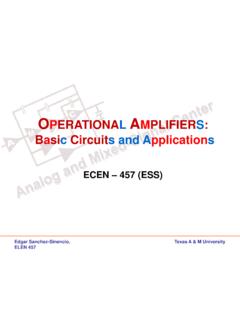
6 Combininga transconductanceamplifierwith a bufferand thenaddingnegativefeedbackproducesthearc hitectureof a current - feedback (CFB) showsa TypicalCFBA mplifierBlockDiagramThe circuitshownin Figure6 makesuse of the OPA860becausethis deviceintegratesbotha buffersectionand an the E-input/-outputis B-inputis the noninvertinginputand the outputof the bufferis C-outputof the OTAis connectedto the high impedanceinputof R1, C1, and C2are parasiticcomponentsof boththe OTAand the an optionalcomponentthat may help de-Qa potentialRLCnetworkas a resultof componentand a sloweramplifierweredesired,to selectthe frequencyresponsea capacitorin parallelwith C2can ,the feedbackresistorRFcan be inputstageof the control-loopamplifiershownin Figure7 is composedof two high inputimpedanceas well as excellentrejectionto any C-outputis left unconnectedand the otherC-outputof the inputstageis connectedto an RCnetwork,in effectformingan integratorfromdc to the frequencydefinedby the RC time thenusedbeforeisolatingthe C-outputof the secondstagewith a buffertoensureac performanceand to Control-LoopAmplifierCircuitModel3B2EC8 CCType DR = 1k12Q,= 1N4148 WJFET-Input, WidebandSOTAHCLVINCHOLDVOUTOTAR1R2R2R1= V OTAA rchitecture7 SBOA117A May 2009 RevisedApril2013 SubmitDocumentationFeedbackCopyright 2009 2013,TexasInstrumentsIncorporatedDemysti fyingthe be developedusinga circuitillustratedinFigure8 usesa SOTAto restorethe signalwhenit is architectureallowsa preciseselectionof the this purpose,we usedthe DC-RestoreCircuitExamplewiththe OPA615In this example,the CHOLD capacitoris beingchargedby the samplingOTA(SOTA),triggeredat the exactpointof OTAprovidesa meansto amplifythe becauseof the very high inputimpedanceof the OTA,a smallCHOLD capacitorcan be usedfor higherfrequencyapplications.
7 Or, if alargeCHOLDis desired,a very low-frequencyhigh-passfilter can be OPA615is the fastestOTAofferedby TexasInstrumentswith a bandwidthin excessof circuitcan easilybeadaptedto operatecontinuouslywithoutany triggerrequirementsby addinga capacitoron the capacitorwill form,with the 100 seriesresistanceat the input,a low-passfilter thatallowsthe SOTAto chargeand dischargethe hold capacitoronly in relationto the low showsanotherpossibleimplementationof a dc-restorecircuitusinga currentconveyorType2(CCII) DC-RestoreCircuitExample(CC Type2) withthe OPA656 Hold/Track50W100W150W100 WOTA21234300W50 WCHOLD22pFVIN10117300 WVOUTSOTAOPA615 AdvancedUsesof May 2009 RevisedApril2013 SubmitDocumentationFeedbackCopyright 2009 2013,TexasInstrumentsIncorporatedDemysti fyingthe OperationalTransconductanceAmplifierHere ,the OTAamplifierworksas a currentconveyor(CCII),with a currentgain of 1. R1and C1set the dcrestorationtime propagationdelayto the dc C1set the outputvoltageof the operationalamplifier(in this case,an OPA656),is comparedto a signalis belowthe level,a currentis driveninto the noninvertinginputof the Amplifier ,therebyraisingthe dc OPA615can also be reconfiguredas a sample/holdcircuitusingthe Sample/HoldCircuitExampleIgnoringthe hold/trackcontrolof the SOTAfor now,or consideringthat the SOTAis in a trackmode,youmay recognizea SOTAis usedas the inputstage,with theOTA(in a bufferconfiguration)to play the outputstagerole of a can see that for any changeof voltageat the input,the outputwill trackthe inputwith a gain of 2 hold mode,the SOTAC-outputis now chargeheld by the hold capacitoris set and droopsonly as a resultof the B-inputbias currentof the outputvoltageis set.
8 The E-outputof the OTAwill thensee a total load of (600 Load).As you go fromtrackmodeto hold mode,you effectivelyrealizea greaterthan700 MHzbandwidth,the OPA615answersseveralmedium-to high- OTAA rchitecture9 SBOA117A May 2009 RevisedApril2013 SubmitDocumentationFeedbackCopyright 2009 2013,TexasInstrumentsIncorporatedDemysti fyingthe showsan instrumentationamplifierusingthreeOPA861 sto formthe OTAsare usedto createthe thirdOTAis presentto invertthe currentflowingout of the the currentis flowingout of the amomentand set a positivevoltageon VIN1. This methodgeneratesa currentthat flowsacrossRGfromtopto bottom,exitingthe IN1 OTAand enteringthe currentflowingout of the C-outputthenflowsout of the IN1 OTAand into the IN2 OTA,indicatingthat bothcurrentswill be of sameamplitudebut180 out of be able to add the currentstogetherat the invertingpin of the operationalamplifier,one of the inputstagecurrentmustbe realizedby the the propagationdelayof the secondamplifier,an RC networkwas the sameamplitudeand phase,we can simplyadd themtogetherand InstrumentationAmplifierApproachwiththe OPA861 Becauseany common-modesignalwill try to generatethe sameopposingcurrentsacrossthe gainresistor,this circuitexhibitsvery =IN+ R1 + sRC1 + 2sRC12sCwo=C C R121Q =12C + CC1C2=11 + sR(C + C )
9 + s C C May 2009 RevisedApril2013 SubmitDocumentationFeedbackCopyright 2009 2013,TexasInstrumentsIncorporatedDemysti fyingthe OperationalTransconductanceAmplifier4 AdvancedOTAC ircuitsFroma conceptualstandpoint,filteringapplicatio nsusingan OTAelementare the mostchallengingbecausethinkingin a current -modeapproachis not a , current -modeamplifiersallowmorebandwidt hfor a reducedquiescentcurrentin sectiondescribesasimplefilteringcircuita s well as a high-performancefilter developedon an low-passfilter circuitillustratedin Figure12 achievesfilteringthroughthe use of a Low-PassFilterCircuitExampleEquation6 providesthe designequationof the filter.(6)with:This circuitmay requiresomebuffering,becausethe inputimpedanceis set as shownin Equation7.(7)s C C R121M2+ sC1F(s) ==VVOUTINRR2M3s C C R121M2RR1M3p+ sC1RR1M2RR1M2pR1p1++ May 2009 RevisedApril2013 SubmitDocumentationFeedbackCopyright 2009 2013,TexasInstrumentsIncorporatedDemysti fyingthe universalactivefilter can be achievedwith an OTAusingan integrator,as Figure13 all OTAsare requiredfor differentfilteringfunctions(suchas low-passfilters,high-passfilters,orband- passfilters).
10 This circuitimplementsa possibleby simplyaddingan additionalintegratorstagewith its two corresponding, UniversalActiveFilterwithOTAA rchitectureWith80 MHzOTAs,filter bandwidthsas high as 50 MHzhavebeenachievedwithoutconsideringany parasiticsfor the ratioof50 MHz/1 GHzthat is achievedwhentraditionaloperationalamplif iercircuitsare givesthe designequationfor the filter shownin Figure13.(8) filter typescan be designedwith this typesincludethe following: For a low-passfilter,set R2= R3= For a high-passfilter,set R1= R2= For a bandpassfilter,set R1= R3= For a bandrejectionfilter,set R2= , and R1= R3 For an all-passfilter,set R1= R1p; R2= R2p; and R3= May 2009 RevisedApril2013 SubmitDocumentationFeedbackCopyright 2009 2013,TexasInstrumentsIncorporatedRevisio nHistoryRevisionHistoryNOTE:Pagenumbersf or previousrevisionsmay differfrompagenumbersin the (May2009)to A its subsidiaries(TI) reservethe rightto makecorrections,enhancements,improvement sand otherchangesto its semiconductorproductsand servicesper JESD46,latestissue,and to discontinueany productor serviceper JESD48, latestrelevantinformationbeforeplacingor dersand shouldverifythat suchinformationis semiconductorproducts(alsoreferredto hereinas components )