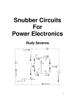
Transcription of Document information AN11160
1 AN11160 Designing RC snubbersRev. 18 May 2021application noteDocument informationInformationContentKeywordsRC snubber , commutation, reverse recovery, leakage inductance, parasitic capacitance, RLCcircuit and damping, MOSFETA bstractThis Document describes the design of a simple rc snubber RC snubbers1. IntroductionThis Document describes the design of a simple rc snubber circuit . The snubber is usedto suppress high-frequency oscillations associated with reverse recovery effects in powersemiconductor Test circuitThe basic circuit is a half-bridge and shown in Fig. driverHS driverinductorQ1 Fig. half-bridge circuitQ1 and Q2 are BUK761R6-40E devices. The inductor could also be connected to 0 V rather thanVDDI nductor current is established in the red loop; Q2 is off and current is flowing through Q1 bodydiode. When Q2 is turned on, current commutates to the blue loop and the reverse recovery effectoccurs in Q1. We observe the effect of Q1 reverse recovery on the VDS waveform of Q2; see Fig.
2 MHzQ2 VDS(5V/div)Fig. recovery-induced oscillation in Q2 VDSAN11160 All information provided in this Document is subject to legal disclaimers. Nexperia 2021. All rights reservedapplication noteRev. 18 May 20212 / 12 NexperiaAN11160 Designing RC snubbersThe equivalent circuit is shown in Fig. (LLK)VDDQ1 Coss(CLK)Q2 VDSQ2 Fig. circuitWe are primarily interested in the parasitic elements in the circuit: LLK is the total stray or leakage inductance comprised of PCB trace inductance, devicepackage inductance, etc. The parasitic capacitance CLK is mainly due to Coss of the upper (Q1) deviceQ2 is treated as a simple switch. The oscillation can be eliminated (snubbed) by placing an RCcircuit across Q1 drain-source; see Fig. (LLK)VDDRSCSQ1 Coss(CLK)Q2 VDSQ2aaa-002744 Fig. circuit with snubber components RS and CS3. Determining CLK and LLKB efore we can design the snubber , we must first determine CLK and LLK. We could attempt tomeasure CLK and LLK directly, but a more elegant method can be used.
3 For this LC circuit, we knowthat:=f 12 RING0 LCLKLK(1)Where fRING0 is the frequency of oscillation without a snubber in place; see Fig. 2. If we add anextra additional capacitor across Q1 (Cadd), the initial oscillation frequency from fRING0 to fRING1(fRING1 < fRING0) will change. It can be shown that (see Section 7):=1xCLKCadd2 (2)where:=fRING1xfRING0(3) AN11160 All information provided in this Document is subject to legal disclaimers. Nexperia 2021. All rights reservedapplication noteRev. 18 May 20213 / 12 NexperiaAN11160 Designing RC snubbersSo if we measure fRING0 (without Cadd), then add a known Cadd and measure fRING1, we candetermine CLK and LLK (two equations, two unknowns).Cadd = 3200 pF was added in circuit, and fRING1 found to be MHz (fRING0 previously found tobe MHz; see Fig. 2).From Equation 3:= (4)and from Equation 2:=1 CLK3200 pF =3239 (5)Rearranging Equation 1:= 12 fRING0 LCLKLK2(((6)So with fRING0 = MHz and CLK = 3239 pF:= 12 LHLK2= (( 10-9nH= (7)and with fRING1 = MHz and (CLK + Cadd) = 3239 pF + 3200 pF = 6439 pF:= 12 LHLK2= (( 10-9nH= (8)In other words, the calculated value of LLK remains almost unchanged when we add the additional3200 pF capacitance.))))))
4 This is a good sanity check of the method for determining CLK and information provided in this Document is subject to legal disclaimers. Nexperia 2021. All rights reservedapplication noteRev. 18 May 20214 / 12 NexperiaAN11160 Designing RC snubbers4. Designing the snubber - theoryIf we replace CS in Fig. 4 with a short-circuit, then we simply have the classic RLC circuit found intext books. The response of this circuit to a step change in voltage (that is Q2 turning on) dependson the degree of damping ( or zeta) in the circuit; see Fig. 5.() (1)(2)(3)(4)(5)(6)(7)(1) = 0.(2) = (3) = (4) = (5) = (6) = 1.(7) = response of an RLC circuit for various values of zeta ( )In theory the circuit oscillates indefinitely if = zero, although this is a practical impossibility asthere is always some resistance in a real circuit. As increases towards one, the oscillationbecomes more damped that is, tends to decrease over time with an exponential decay is an under-damped response.
5 The case = one is known as critically damped and is thepoint at which oscillation just ceases. For values of greater than one (over-damped), the responseof the circuit becomes more sluggish with the waveform taking longer to reach its final value. Thereis therefore more than one possible degree of damping which we could build into a snubber , andchoice of damping is therefore part of the snubber design this configuration of RLC circuit, the relationship between , RS, LLK and CLK is: = 1L2 RLKS CLK(((9)The snubber capacitor CS does not appear in Equation some circuits, it is possible to damp the oscillations with RS alone. However, in typical half-bridgecircuits we cannot have a resistor mounted directly across Q1 drain source. If we did, then Q1 ispermanently shorted by the resistor and the circuit as a whole would not function as required. Thesolution is therefore to put CS in series with RS, with the value of CS chosen so as not to interferewith normal snubber is a straightforward RC circuit whose cut-off frequency fC is:=F 12 CRCSS(10) AN11160 All information provided in this Document is subject to legal disclaimers.))
6 Nexperia 2021. All rights reservedapplication noteRev. 18 May 20215 / 12 NexperiaAN11160 Designing RC snubbersAgain, we must choose which value of fC to be used, and there is no single correct answer to thisquestion. The cut-off frequency of the snubber must be low enough to effectively short-circuit theundamped oscillation frequency fRING0, but not so low as to present a significant conduction path atthe operating frequency of the circuit (for example 100 kHz or whatever). A good starting point hasbeen found to be fC = Designing the snubber - in practiceWe now have sufficient information to design a snubber for the waveform shown in Fig. 2. To recap:CLK = 3239 pFLLK = nHfRING0 = MHz = 1L2 RLKS CLK(((11)=F 12 CRCSS=fRING0(12)The first task is to choose a value of damping (Fig. 5). We have chosen = 1, that is, criticaldamping. Rearranging Equation 11 we have: = 1 LRLKS CLK((2= 1((2 = (13)use 2 in parallel to give.))))))
7 Rearranging Equation 12 we have:= 1CS= = nF2 RSfRING02 1(14)use nF + nF to give snubber was fitted across Q1 drain source. The resulting waveform is shown in Fig. 6 togetherwith the original (non-snubbed) waveform from Fig. information provided in this Document is subject to legal disclaimers. Nexperia 2021. All rights reservedapplication noteRev. 18 May 20216 / 12 NexperiaAN11160 Designing RC snubbersaaa-002746a. Without snubberVertical scale is 2 With snubberFig. VDS waveform with and without snubberAs seen in Fig. 6 the snubber has almost eliminated the ringing in the VDS waveform. Thistechnique could also be applied to the MOSFET in the Q2 Summary Reverse recovery effects in power devices can induce high frequency oscillations in devicesconnected to them A common technique for suppressing the oscillations is the use of an rc snubber . Design of an effective snubber requires the extraction of the circuit parasitic capacitance andinductance.
8 A method has been demonstrated for doing this. The snubbed circuit has been shown to be a variation on the classic RLC circuit. A method of determining values of snubber components has been demonstrated. The methodhas been shown to work well, using the example of BUK761R6-40E MOSFETs7. Appendix A; determining CLK from Cadd, fRING0 and fRING1We know that:=f 12 RING0 LCLKLK(15)where fRING0 is the frequency of oscillation without a snubber in place and LLK and CLK are theparasitic inductances and capacitances we add capacitor Cadd across Q1 drain-source, fRING0 is reduced by an amount x where:=xfRING0((LCLKLK 12 Cadd+(16)therefore=((LCLKLK 2 Cadd+ 12 LCLKLKx(17) AN11160 All information provided in this Document is subject to legal disclaimers. Nexperia 2021. All rights reservedapplication noteRev. 18 May 20217 / 12 NexperiaAN11160 Designing RC snubbers=((LCLKLK Cadd+ 1 LCLKLKx(18)=((LCLKLK Cadd+LCLKLKx(19)=xCLK2 CLKCadd+(20)=CLKC addx2 CLK(21)xCLK1 ))=Cadd2(22)CLK=Caddx1 2(23)where:=fRING1xfRING0(24)8.))))))
9 Revision historyTable 1. Revision revised to use latest Nexperia branding and legal information provided in this Document is subject to legal disclaimers. Nexperia 2021. All rights reservedapplication noteRev. 18 May 20218 / 12 NexperiaAN11160 Designing RC snubbers9. Legal informationDefinitionsDraft The Document is a draft version only. The content is still underinternal review and subject to formal approval, which may result inmodifications or additions. Nexperia does not give any representations orwarranties as to the accuracy or completeness of information included hereinand shall have no liability for the consequences of use of such warranty and liability information in this Document is believedto be accurate and reliable. However, Nexperia does not give anyrepresentations or warranties, expressed or implied, as to the accuracyor completeness of such information and shall have no liability for theconsequences of use of such information .
10 Nexperia takes no responsibilityfor the content in this Document if provided by an information source outsideof no event shall Nexperia be liable for any indirect, incidental, punitive,special or consequential damages (including - without limitation - lostprofits, lost savings, business interruption, costs related to the removalor replacement of any products or rework charges) whether or not suchdamages are based on tort (including negligence), warranty, breach ofcontract or any other legal any damages that customer might incur for any reasonwhatsoever, Nexperia s aggregate and cumulative liability towards customerfor the products described herein shall be limited in accordance with theTerms and conditions of commercial sale of to make changes Nexperia reserves the right to make changesto information published in this Document , including without limitationspecifications and product descriptions, at any time and without notice. Thisdocument supersedes and replaces all information supplied prior to thepublication for use Nexperia products are not designed, authorized orwarranted to be suitable for use in life support, life-critical or safety-criticalsystems or equipment, nor in applications where failure or malfunctionof an Nexperia product can reasonably be expected to result in personalinjury, death or severe property or environmental damage.