Transcription of Dual Channel, High IP3, 100 MHz to 6 GHz Active …
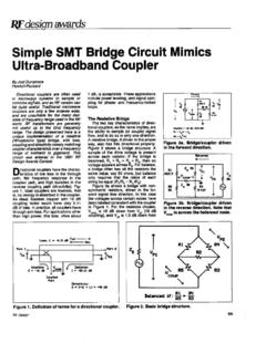
1 Dual Channel, High IP3, 100 MHz to 6 GHz Active Mixer data sheet adl5802 FEATURES Power conversion gain of dB Wideband RF, LO, and IF ports SSB noise figure of 11 dB Input IP3 of 28 dBm Input P1dB of 12 dBm Typical LO drive of 0 dBm Low LO leakage Single supply operation: 5 V @ 240 mA Exposed paddle, 4 mm 4 mm, 24-lead LFCSP package APPLICATIONS Cellular base station receivers Main and diversity receiver designs Radio link downconverters FUNCTIONAL BLOCK DIAGRAM 07882-001 GNDENBLLOIPLOINVPOSGNDOP2+RF1 RF1+VPOS7815161718212223 ADL58021920RF2 GND1314 GNDVSETGNDGNDGNDGNDRF2+OP2 VPOSGNDOP1+OP1 654321249101112IP3 BIAS Figure 1.
2 GENERAL DESCRIPTION The adl5802 uses high linearity, double-balanced, Active mixer cores with integrated LO buffer amplifiers to provide high dynamic range frequency conversion from 100 MHz to 6 GHz. The mixers benefit from a proprietary linearization architecture that provides enhanced input IP3 performance when subject to high input levels. A bias adjust feature allows the i npu t l i n e a r it y, SSB noise figure, and dc current to be optimized using a single control pin. The high input linearity allows the device to be used in demanding cellular applications where in-band blocking signals may otherwise result in degradation in dynamic perform-ance.
3 The balanced Active mixer arrangement provides superb LO to RF and LO to IF leakage, typically better than 30 dBm. The IF outputs are designed for a 200 source impedance and provide a typical voltage conversion gain of dB when loaded into a 200 load. The adl5802 is fabricated using a SiGe high performance IC process. The device is available in a compact 4 mm 4 mm, 24-lead LFCSP package and operates over a 40 C to +85 C temperature range. An evaluation board is also available. Rev. B Document Feedback Information furnished by Analog Devices is believed to be accurate and reliable. However, no responsibility is assumed by Analog Devices for its use, nor for any infringements of patents or other rights of third parties that may result from its use.
4 Specifications subject to change without notice. No license is granted by implication or otherwise under any patent or patent rights of Analog Devices. Trademarks and registered trademarks are the property of their respective owners. One Technology Way, Box 9106, Norwood, MA 02062-9106, Tel: 2009 2015 Analog Devices, Inc. All rights reserved. Technical Support adl5802 data sheet TABLE OF CONTENTS Features .. 1 Applications .. 1 Functional Block Diagram .. 1 General Description .. 1 Revision History .. 2 Specifications .. 3 Absolute Maximum Ratings .. 5 ESD Caution .. 5 Pin Configuration and Function Descriptions.
5 6 Typical Performance Characteristics .. 7 Downconverter Mode Using a Broadband Balun .. 7 Downconverter Mode Using a Johanson GHz Balun .. 12 Downconverter Mode Using a Johanson GHz Balun .. 15 Downconverter Mode Using a Johanson GHz Balun .. 18 Spur Performance .. 21 Circuit 24 LO Amplifier and 24 RF Voltage to Current (V-to-I) Converter .. 24 Mixer Cores .. 24 Mixer Load .. 24 Bias Circuit .. 24 Applications Information .. 25 Basic Connections .. 25 RF and LO Ports .. 25 IF Port .. 26 Evaluation Board .. 27 Outline Dimensions .. 29 Ordering Guide .. 29 REVISION HISTORY 2/15 Rev. A to Rev. B Updated Outline Dimensions.
6 29 Changes to Ordering Guide .. 29 6/12 Rev. 0 to Rev. A Changes to Downconverter Mode Using a Broadband Balun Section and Figure 6 .. 7 Changes to Figure 11 .. 8 Changes to Figure 17, Figure 18, Figure 19, and Figure 20 .. 9 Changes to Figure 27 .. 11 Changed Downconverter Mode Using a Johanson GHz Balun Section to Downconverter Mode Using a Johanson GHz Balun Section .. 12 Changes to Downconverter Mode Using a Johanson GHz Balun Section and Figure 31 .. 12 Changes o Figure 35 and Figure 36 .. 13 Changes to Figure 40 .. 14 Changes to Downconverter Mode Using a Johanson GHz Balun Section and Figure 44 .. 15 Changes to Figure 48 and Figure 49.
7 16 Changes to Figure 53 .. 17 Changed Downconverter Mode Using a Johanson GHz Balun Section to Downconverter Mode Using a Johanson GHz Balun Section .. 18 Changes to Downconverter Mode Using a Johanson GHz Balun Section .. 18 Changes to Figure 61 and Figure 62 .. 19 Changes to Figure 20 .. 20 Changes to 900 MHz Performance Section and 2090 MHz Performance Section .. 21 Changes to 2600 MHz Performance Section and 3500 MHz Performance Section .. 22 Changes to 5800 MHz Performance Section .. 23 Updated Outline Dimensions .. 29 11/09 Revision 0: Initial Version Rev. B | Page 2 of 32 data sheet adl5802 SPECIFICATIONS VS = 5 V, VSET = 4 V, TA = 25 C, fLO = (fRF 153) MHz, LO power = 0 dBm, Z01 = 50 , unless otherwise noted.
8 Table 1. Parameter Test Conditions/Comments Min Typ Max Unit RF INPUT INTERFACE Return Loss Tunable to >20 dB over a limited bandwidth 18 dB Input Impedance 50 RF Frequency Range 100 6000 MHz OUTPUT INTERFACE Output Impedance Differential impedance, f = 200 MHz 240 IF Frequency Range Can be matched externally to 3000 MHz LF 600 MHz DC Bias Voltage2 Externally generated VS V LO INTE R FAC E LO Power 10 0 +10 dBm Return Loss 18 dB Input Impedance 50 LO Frequency Range 100 6000 MHz POWER INTERFACE Supply Voltage 5 V Quiescent Current Resistor programmable 220 300 mA Disable Current ENBL pin low 170 mA Enable Time Time from ENBL pin low to power-up 182 ns Disable Time Time from ENBL pin high to power-down 28 ns DYNAMIC PERFORMANCE at fRF = 900 MHz/1900 MHz Power Conversion Gain3 fRF = 900 MHz dB fRF = 1900 MHz dB
9 Voltage Conversion Gain4 fRF = 900 MHz dB fRF = 1900 MHz dB SSB Noise Figure fCENT = 900 MHz 10 dB fCENT = 1900 MHz 11 dB SSB Noise Figure Under Blocking5 fCENT = 900 MHz 18 dB fCENT = 1900 MHz 22 dB Input Third Order Intercept6 fCENT = 890 MHz 26 dBm fCENT = 1890 MHz 28 dBm Input Second Order Intercept7 fCENT = 890 MHz 60 dBm fCENT = 1890 MHz 45 dBm Input 1 dB Compression Point fRF = 900 MHz 12 dBm fRF = 1900 MHz 12 dBm LO to IF Output Leakage Unfiltered IF output 35 dBm LO to RF Input Leakage 30 dBm RF to IF Output Isolation 25 dBc RFI1 to RFI2 Channel Isolation 45 dBc IF/2 Spurious8 0 dBm input power, fRF = 900 MHz 68 dBc IF/3 Spurious8 0 dBm input power, fRF = 900 MHz 67 dBc IF/2 Spurious8 0 dBm input power, fRF = 1900 MHz 53 dBc IF/3 Spurious8 0 dBm input power, fRF = 1900 MHz 59 dBc DYNAMIC PERFORMANCE at fRF = 2500 MHz9 Power Conversion Gain10 dB Voltage Conversion Gain4 dB SSB Noise Figure dB SSB Noise Figure Under Blocking11 fCENT = 2145 MHz 18 dB Input Third Order Intercept6 fCENT = 2500 MHz 30 dBm Rev.
10 B | Page 3 of 32 adl5802 data sheet Parameter Test Conditions/Comments Min Typ Max Unit Input Second Order Intercept7 fCENT = 2500 MHz 47 dBm Input 1 dB Compression Point 13 dBm LO to IF Output Leakage Unfiltered IF output 36 dBm LO to RF Input Leakage 31 dBm RF to IF Output Isolation 26 dBc RFI1 to RFI2 Channel Isolation 42 dBc IF/2 Spurious8 0 dBm input power 52 dBc IF/3 Spurious8 0 dBm input power 56 dBc DYNAMIC PERFORMANCE at fRF = 3500 MHz12 Power Conversion Gain13 dB Voltage Conversion Gain4 dB SSB Noise Figure dB SSB Noise Figure Under Blocking14 fCENT = 3500 MHz 18 dB Input Third Order Intercept5 fCENT = 3500 MHz 25 dBm Input Second Order Intercept7 fCENT = 3500 MHz 39 dBm Input 1 dB Compression Point 13 dBm LO to IF Output Leakage Unfiltered IF output 33 dBm LO to RF Input Leakage 28 dBm RF to IF Output Isolation 31 dBc RFI1 to RFI2 Channel Isolation 39 dBc IF/2 Spurious8 0 dBm input power 46 dBc IF/3 Spurious8 0 dBm input power 63 dBc DYNAMIC PERFORMANCE at fRF = 5500 MHz15 Power Conversion Gain16 3 dB Voltage Conversion Gain4 dB SSB Noise Figure 14 dB SSB Noise Figure Under Blocking17 fCENT = 5800 MHz 17 dB Input Third Order Intercept5