Transcription of EN 1997-1 Eurocode 7
1 Brussels, 18-20 February 2008 Dissemination of information workshop1 EUROCODESB ackground and ApplicationsEN 1997 1: Sections 3 and 6 Your logoEN 1997-1 Eurocode 7 Section 3 Geotechnical DataSection 6 Spread FoundationsTrevor OrrTrinity College Dublin IrelandEurocode 7 Workshop Brussels 20thFebruary 2008 Brussels, 18-20 February 2008 Dissemination of information workshop2 EUROCODESB ackground and ApplicationsSection 3EN 1997-1 : Section 3 Geotechnical DataBrussels, 18-20 February 2008 Dissemination of information workshop3 EUROCODESB ackground and ApplicationsSection 3 Overview The fact that EN 1997-1 has a separate section on Geotechnical Data demonstrates that the determination of geotechnical datais an essential part of the geotechnical design process This is because soil is a natural material, unlike the manufactured materials in the other structural Eurocodes, where the data for these materials is specified Section 3 Geotechnical Dataprovides the general requirements for: the collectionof geotechnical data the evaluation of geotechnical parameters The presentation of geotechnical information It is linked to Section 2which presents the factors to be consideredwhen determininggeotechnical parameter values and the requirements for selecting characteristic values It is also linked to EN 1997.
2 Part 2which gives the requirements for deriving the valuesof geotechnical parameters from field and laboratory testsBrussels, 18-20 February 2008 Dissemination of information workshop4 EUROCODESB ackground and ApplicationsGeotechnical Investigations The importance of carefully planned, appropriately executedand reportedinvestigations that provide sufficient data concerning the ground is stressed in and Provisions for two types of investigations are given: Preliminaryinvestigations Designinvestigations Control investigations Requirements are given for the reportingof ground investigations in a Ground Investigation ReportBrussels, 18-20 February 2008 Dissemination of information workshop5 EUROCODESB ackground and ApplicationsStages in Determining Parameter Values The procedures involved in determining the design valuesof geotechnical parameters from field or laboratory test resultsmay be considered as consisting of three stages or steps(Frank et al.)
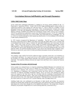
3 2004) The first stepis to go from measured values, taking account of the test conditions, and assess the geotechnical parameter values( the properties of soil or rock at a particular location in the ground) and The second stepis to take account of the design situation and assess the characteristic valueas a cautious estimate of the geotechnical parameter values affecting the occurrence the limit state The third stepis to obtain the design parameter valueby applying a partial factor to the characteristic value , 18-20 February 2008 Dissemination of information workshop6 EUROCODESB ackground and ApplicationsCharacteristic Values from Measured ValuesMeasured ValuesStep 1 Covered by:EN 1997-1 ,Clauses , 1997-2 Test ResultsResults of field tests at particular pointsin the ground or locations on a site or laboratory tests on particular specimensTest related correction, independent of any further analysis Theory, empirical relationships or correlations to obtain Derived valuesAssessment of influence of test and design conditions on parameter valueSelection of relevant test results peak or constant volume strengthsGeotechnical Parameter ValuesQuantified for design calculationsCautious estimate of geotechnical parameter value taking account of.
4 Test conditions, Nature of ground Particular limit state, Nature of structureCharacteristic Parameter ValueStep 2 Covered byEN 1997-1 , Clause , 18-20 February 2008 Dissemination of information workshop7 EUROCODESB ackground and ApplicationsEvaluation of Geotechnical Parameters The factors to be consideredwhen evaluating soil and rock parameters are given in the following sub-sections of : Characteristics of soil and rock types Weight density Density index Degree of compaction Soil shear strength Soil stiffness Quality and properties of rock masses Permeability and consolidation parameters of soil and rock Geotechnical parameters from field tests: CPT SPT Vane test Weight sounding test Pressuremeter test Dilatometer test Compactability testBrussels, 18-20 February 2008 Dissemination of information workshop8 EUROCODESB ackground and ApplicationsGround Investigation Report Section 3 states that the results of a geotechnical investigation shall be presented in a Ground Investigation Report The Ground Investigation Report should form part of the Geotechnical Design Report A comprehensive list of items to be included in this report is provided The Ground Investigation Report should normally include: A presentation of all the geotechnical information a factual report A geotechnical evaluation of the information, stating the assumptions made in the interpretation of the test results an interpretative reportBrussels, 18-20 February 2008 Dissemination of information workshop9 EUROCODESB ackground and ApplicationsSection 6EN 1997-1 .
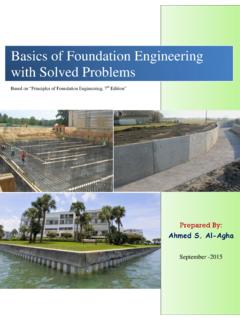
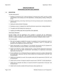
5 Section 6 Spread FoundationsBrussels, 18-20 February 2008 Dissemination of information workshop10 EUROCODESB ackground and ApplicationsLimit States Provisions apply to pads, strip and raftfoundations Relevant to foundations for gravity retaining wallsand bridgesas well as buildings List of limit statesto be considered and compiled is given: Loss of overall stability Bearing resistance failure Failure by sliding Combined failure in ground and structure Structural failure due to ground movement Excessive settlements Excessive heave due to swelling frost heave and other causes Unacceptable vibrations Some of above are ultimate limit states and some are serviceability limit states both need to be considered Note term bearing resistance is used instead of bearing capacity Failure by overturningis nota relevant limit state failure by bearing resistance will occur firstBrussels, 18-20 February 2008 Dissemination of information workshop11 EUROCODESB ackground and ApplicationsControlling Limit width (m)Design bearing pressure (kPa)ULSSLSAs theloadthat a foundation has to supportincreases, and hence as the foundationwidth increases, thecontrolling limit state changesfrom bearing failure (ULS) to excessive settlement (SLS).
6 Henceneed to check both ULS andSLSB russels, 18-20 February 2008 Dissemination of information workshop12 EUROCODESB ackground and ApplicationsCalculation Model EquilibriumEquation to be satisfiedFd Rd Equation is in terms of forces, notensuring stresses do not exceed the allowable stress, as in traditional design Hence the modelfor bearing resistance failure is a rectangular plastic stress blockat the limiting stress beneath the foundation, similar to the plastic stress block in the ultimate limit state design of a concrete beam The design bearing resistance force, Rdacts through the centreof this stress block over effective foundation area,A Need to consider both drainedand undrainedconditions FV, FHM, W1W2 RdAVPVdAHfrom Frank et , 18-20 February 2008 Dissemination of information workshop13 EUROCODESB ackground and ApplicationsDesign MethodDirect Method Carry out a separate analysis for each limit state.
7 Calculation method shall model as closely as possible the failure mechanism envisaged, Bearing resistance model for ULS Settlement calculation for SLSI ndirect Method Using comparable experience and field or laboratory measurements or observations, chosen in relation to SLS loads, so as satisfy the requirements of all limit states Example: considering SLSfor conventional structures founded on clays, the ratio between the bearing resistance of the ground, at its initial characteristic shear strength, to the applied serviceability loading, Ru,k/ Fk, should be calculated ( (16)): If Ru,k/ Fk< 3, calculation of settlements should always be undertaken If Ru,k/ Fk< 2, calculation of settlements should take account of non-linear stiffness effectsof the groundBrussels, 18-20 February 2008 Dissemination of information workshop14 EUROCODESB ackground and ApplicationsSpread Foundation ExampleDesign Situation:Square pad foundation for a building, embedment depth; groundwater level at base of foundation.
8 Central vertical load. Allowable settlement is values of actions:Permanent vertical load = 900 kN + weight of foundationVariable vertical load = 600 kNConcrete weight density = 24 Properties:Overconsolidated glacial till, cu;k= 200 kPa, c'k= 0kPa, 'k= 35o, k= 22kN/m3 SPT N = 40, mv;k= m2 foundation width, BTo satisfy both ULS(drained and undrained conditions) and SLSU sing recommended partial factors valuesGk= 900kN, Qk= 600kNGWLB = ?d = m Brussels, 18-20 February 2008 Dissemination of information workshop15 EUROCODESB ackground and ApplicationsDirect MethodULScalculations for 3 Design Approaches DA1 -Combination 1 Combination 2 DA2 DA3 For: Undrained Conditions Drained ConditionsSLScalculationBrussels, 18-20 February 2008 Dissemination of information workshop16 EUROCODESB ackground and ApplicationsUndrained ConditionsGeneral Equation for undrained design bearing resistanceRu;d/ A for all Design ApproachesAnnex D - Eqn.
9 :Ru;d/ A = (( + 2) cu;dbcscic+ qd) / R= (( + 2)(cu,k/ cu) bcscic+ qk) / R= (( + 2)(cu;k/ cu) bcscic+ d) / Rwhere : cu;k, cu;d= characteristic and design values of cubc= for a horizontal foundation basesc = for a square foundation andic = for a vertical load` = = weight density of the soil cu= partial factor on cu = partial factor on soil weight density, always = R= partial resistance factor Substituting known values in Eqn. :Ru;d/ A = ( x (200 / cu ) x x x + x 22 x ) / R= ( x 200 / cu+ ) / RGeneral Equation: Ru;d/A = ( / cu+ ) / RBrussels, 18-20 February 2008 Dissemination of information workshop17 EUROCODESB ackground and ApplicationsDesign for DA1 Undrained ConditionsDesign Approach 1 Combination 1 Check Vd Rdfor a m x m pad, where Vd= Fd- Design value of the vertical actionVd= G(Gk+ Gpad;k) + QQk= G(Gk+ A cd) + QQkwhere Gpad;k= characteristic weight of the concrete pad, c= weight density of concrete, d = depth of the pad and Q= partial factor on variable actions.
10 Substituting values for parameters gives:Vd= (900 + x ) + x 600 = kN- Design value of the bearing resistanceRd= ( / cu+ ) / R = ( / + ) / = kNThe ULS design requirement Vd Rdis fulfilledas kN < Approach 1 Combination 2 Check Vd Rdfor a m x m pad- Design value of the vertical actionVd= G(Gk+ Gpad;k) + QQk= (900 + x ) + x 600 = kN- Design value of the bearing resistanceRd= ( / + ) / = kNThe ULS design requirement Vd Rdis fulfilledas kN < kNSince B = for > B = for Design Width for Undrained Conditions: DA1 = (given by )Brussels, 18-20 February 2008 Dissemination of information workshop18 EUROCODESB ackground and ApplicationsDesigns for DA2 and DA3 Undrained ConditionsDesign Approach 2 Check Vd Rdfor a m x m pad- Design value of the vertical actionVd= G(Gk+ A cd) + QQkVd= (900 + x ) + x 600 = kN- Design value of the bearing resistanceRd= ( / cu+ ) / R = ( / + ) / = kNThe ULS design requirement Vd Rdis fulfilledas kN < Design Width for Undrained Conditions:DA2 = Approach 3 Check Vd Rdfor a m x m pad- Design value of the vertical actionVd= G(Gk+ Gpad.)