Transcription of FEATURES DESCRIPTIO U - analog.com
1 LT1025. Micropower thermocouple Cold Junction Compensator U. FEATURES DESCRIPTIO . 80 A Supply Current The LT 1025 is a micropower thermocouple cold junction 4V to 36V Operation compensator for use with type E, J, K, R, S, and T. C Initial Accuracy (A Version) thermocouples. It utilizes wafer level and post-package Compatible with Standard Thermocouples trimming to achieve C initial accuracy. Special curvature (E, J, K, R, S, T) correction circuitry is used to match the bow found in all Auxiliary 10mV/ C Output thermocouples so that accurate cold junction compensation Available in 8-Lead PDIP and SO Packages is maintained over a wider temperature range. U The LT1025 will operate with a supply voltage from 4V to 36V. APPLICATIO S Typical supply current is 80 A, resulting in less than C.
2 Internal temperature rise for supply voltages under 10V. thermocouple Cold Junction Compensator A 10mV/ C output is available at low impedance, in addition Centigrade Thermometer to the direct thermocouple voltages of V/ C (E), Temperature Compensation Network V/ C (J), V/ C (K, T) and V/ C (R, S). All outputs are essentially independent of power supply voltage. A special kit is available (LTK001) which contains an LT1025. and a custom tailored thermocouple amplifier. The amplifier and compensator are matched to allow a much tighter specifi- cation of temperature error than would be obtained by adding the compensator and amplifier errors on a worst-case basis. The amplifier from this kit is available separately as LTKA0x. The LT1025 is available in either an 8-pin PDIP or 8-pin SO.
3 Package for temperatures between 0 C and 70 C. , LTC and LT are registered trademarks of Linear Technology Corporation. W U. BLOCK DIAGRA TYPICAL APPLICATIO. Type K 10mV/ C Thermometer E V/ C R2 R3**. VIN 100 255k J V/ C. FULL-SCALE TRIM 1%. +. BUFFER K,T V/ C R1. BOW*. 1k V+. CORRECTION 1% C2. VOLTAGE V+ . R, S 6 V/ C F VOUT. LTKA0x . VIN 10mV/ C. 10mV/ C. TEMPERATURE. K. + +. V . SENSOR R COMMON LT1025 *R4 30 A , R4 IS NOT REQUIRED. V . V0 10mV/ C VO TYPE K (OPEN) FOR LT1025 TEMPERATURES 0 C. GND R C1. R4* F **SELECTED FOR 0 C TO 100 C RANGE. *CORRECTS FOR BOW GND OR. EQUIVALENT. SEE. IN COLD JUNCTION, NOT AMPLIFIER CONSIDERATIONS . IN PROBE (HOT JUNCTION) LT1025 BD01 V . LT1025 TA01. 1025fb 1. LT1025. W W W U U W U. ABSOLUTE AXI U RATI GS PACKAGE/ORDER I FOR ATIO.
4 (Note 1). Input Supply Voltage .. 36V. TOP VIEW ORDER PART. Output Voltage (Forced).. 5V. E. V/ C 1 8. J. V/ C NUMBER. VIN 2 K, T. Output Short-Circuit Duration .. Indefinite 7 V/ C LT1025 ACN8. VO 3 R, S. Operating Temperature Range 10mV/ C 6 6 V/ C LT1025CN8. R . GND 4 5. LT1025AC, LT1025C ..0 C to 70 C COMMON LT1025CS8. LT1025AM, LT1025M .. 55 C to 125 C N8 PACKAGE S8 PACKAGE. 8-LEAD PDIP 8-LEAD PLASTIC SO S8 PART MARKING. Storage Temperature Range .. 55 C to 150 C TJMAX = 150 C, JA = 130 C/W (N8). TJMAX = 150 C, JA = 190 C/W (S8) 1025. J8 PACKAGE 8-LEAD CERDIP LT1025 AMJ8. TJMAX = 150 C, JA = 100 C/W. LT1025MJ8. OBSOLETE PACKAGE. Consider the N8 Package for Alternate Source Consult LTC Marketing for parts specified with wider operating temperature ranges. ELECTRICAL CHARACTERISTICS The denotes the specifications which apply over the full operating temperature range, otherwise specificatons are at TA = 25 C.
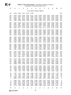
5 VS = 5V, Pin 5 tied to Pin 4, unless otherwise noted. PARAMETER CONDITIONS MIN TYP MAX UNITS. Temperature Error at TJ = 25 C. 10mV/ C Output (Notes 4, 5) LT1025A C. LT1025 C. Full Temperature Span See Curve Resistor Divider Accuracy VOUT = 10mV/ C. (Notes 2, 4) LT1025A E V/ C. J V/ C. K, T V/ C. R, S V/ C. LT1025 E V/ C. J V/ C. K, T V/ C. R, S V/ C. Supply Current 4V VIN 36V 50 80 100 A. LT1025AC, LT1025C 50 150 A. LT1025AM, LT1025M 200 A. Line Regulation (Note 3) 4V VIN 36V C/V. Load Regulation (Note 3) 0 IO 1mA C. Divider Impedance E k . J k . K, T k . R, S k . Change in Supply Current 4V VIN 36V A/V. Note 1: Absolute Maximum Ratings are those values beyond which the Note 4: To calculate total temperature error at individual thermocouple life of a device may be impaired.
6 Outputs, add 10mV/ C output error to the resistor divider error. Total error Note 2: Divider accuracy is measured by applying a signal to the for type K output at 25 C with an LT1025A is C plus ( V/ C)(25 C)/. output divider and measuring the individual outputs. ( V/ C) = C + C = C. Note 3: Regulation does not include the effects of self-heating. See Note 5: Temperature error is defined as the deviation from the following Internal Temperature Rise in Application Guide. Load regulation is formula: VOUT = 10mV(T) + (10mV)( 10-4)(T 25 C)2. The second 30 A IO 1mA for TA 0 C. term is a built-in nonlinearity designed to help compensate the nonlinearity of the cold junction. This bow is C for a 25 C temperature change. 1025fb 2. LT1025. U W. TYPICAL PERFOR A CE CHARACTERISTICS.
7 10mV/ C Output Temperature 10mV/ C Output Temperature Error LT1025 Error LT1025A Supply Current 10 5 200. DOES NOT INCLUDE 30 A. 8 4 180 PULL-DOWN CURRENT. GUARANTEED LIMITS* GUARANTEED LIMITS* REQUIRED FOR TEMPERATURES. 6 3 160. TEMPERATURE ERROR ( C). TEMPERATURE ERROR ( C). LT1025 LT1025A BELOW 0 C. 4 2 140. TJ = 125 C. CURRENT ( A). 2 1 120. 0 0 100. 2 1 80. TJ = 25 C. 4 2 60. 6 3 40. TJ = 55 C. 8 4 20. PIN 4 TIED TO PIN 5. 10 5 0. 50 25 0 25 50 75 100 125 50 25 0 25 50 75 100 125 0 5 10 15 20 25 30 35 40. JUNCTION TEMPERATURE ( C) JUNCTION TEMPERATURE ( C) SUPPLY VOLTAGE (V). LT1025 G01 LT1025 G02 LT1025 G03. *ERROR CURVE FACTORS IN THE NONLINEARITY *ERROR CURVE FACTORS IN THE NONLINEARITY. TERM BUILT IN TO THE LT1025. SEE THEORY OF TERM BUILT IN TO THE LT1025. SEE THEORY OF.
8 OPERATION IN APPLICATION GUIDE SECTION OPERATION IN APPLICATION GUIDE SECTION. U U W U. APPLICATIO S I FOR ATIO. The LT1025 was designed to be extremely easy to use, but To date, IC manufacturers efforts to make microminiature the following ideas and suggestions should be helpful in thermos bottles have not been totally successful. There- obtaining the best possible performance and versatility fore, an electronically simulated cold-junction is required from this new cold junction compensator. for most applications. The idea is basically to add a temperature dependent voltage to VS such that the voltage Theory of Operation sum is the same as if the T2 junction were at a constant 0 C. A thermocouple consists of two dissimilar metals joined instead of at room temperature.
9 This voltage source is together. A voltage (Seebeck EMF) will be generated if the called a cold junction compensator. Its output is designed two ends of the thermocouple are at different to be 0V at 0 C and have a slope equal to the Seebeck temperatures. In Figure 1, iron and constantan are joined coefficient over the expected range of T2 temperatures. at the temperature measuring point T1. Two additional Fe Cu thermocouple junctions are formed where the iron and TEMPERATURE T1. constantan connect to ordinary copper wire. For the TO BE MEASURED. CONSTANTAN. T2. Cu } VS. purposes of this discussion it is assumed that these two LT1025 MUST BE LOCATED. NEXT TO COLD JUNCTION. junctions are at the same temperature, T2. The Seebeck FOR TEMPERATURE TRACKING. voltage, VS, is the product of the Seebeck coefficient , LT1025 AG01.
10 Figure 1. and the temperature difference, T1 T2; VS = (T1 T2). The junctions at T2 are commonly called the cold junction To operate properly, a cold junction compensator must be because a common practice is to immerse the T2 junction at exactly the same temperature as the cold junction of the in 0 C ice/water slurry to make T2 independent of room thermocouple (T2). Therefore, it is important to locate the temperature variations. thermocouple tables are based LT1025 physically close to the cold junction with local on a cold-junction temperature of 0 C. temperature gradients minimized. If this is not possible, 1025fb 3. LT1025. U U W U. APPLICATIO S I FOR ATIO. an extender made of matching thermocouple wire can be temperatures below zero unless an external pull-down used.