Transcription of FEATURES DESCRIPTIO U - analog.com
1 1LT136050 MHz, 800V/ s Op AmpnWideband AmplifiersnBuffersnActive FiltersnVideo and RF AmplificationnCable DriversnData Acquisition Systemsn50 MHz Gain Bandwidthn800V/ s Slew Raten5mA Maximum Supply Currentn9nV/ Hz Input Noise VoltagenUnity-Gain StablenC-LoadTM Op Amp Drives All Capacitive Loadsn1mV Maximum Input Offset Voltagen1 A Maximum Input Bias Currentn250nA Maximum Input Offset Currentn 13V Minimum Output Swing into 500 n Minimum Output Swing into 150 Minimum DC Gain, RL=1kn60ns Settling Time to , 10V Differential Gain, AV=2, RL=150 Differential Phase, AV=2, RL=150 nSpecified at , 5V, and 15 VThe LT1360 is a high speed, very high slew rate opera-tional amplifier with excellent DC performance.
2 The LT1360features reduced supply current, lower input offset volt-age, lower input bias current and higher DC gain thandevices with comparable bandwidth. The circuit topologyis a voltage feedback amplifier with the slewing character-istics of a current feedback amplifier. The amplifier is asingle gain stage with outstanding settling characteristicswhich makes the circuit an ideal choice for data acquisitionsystems. The output drives a 500 load to 13V with 15 Vsupplies and a 150 load to on 5V supplies. Theamplifier is also capable of driving any capacitive loadwhich makes it useful in buffer or cable driver LT1360 is a member of a family of fast, highperformance amplifiers using this unique topology andemploying Linear Technology Corporation s advancedbipolar complementary processing.
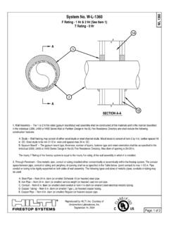
3 For dual and quadamplifier versions of the LT1360 see the LT1361/LT1362data sheet. For 70 MHz amplifiers with 6mA of supplycurrent per amplifier see the LT1363 and LT1364/LT1365data sheets. For lower supply current amplifiers withbandwidths of 12 MHz and 25 MHz see the LT1354through LT1359 data sheets. Singles, duals and quads ofeach amplifier are Op Amp Instrumentation Amplifier1360 TA01 VINTRIM R5 FOR GAINTRIM R1 FOR COMMON-MODE REJECTIONBW = 500kHzR110kR21kR5220 R410kR31kVOUT+ + +LT1360LT1360 GAINRRRRRRRRR= + + ++() =431122134235102AV = 1 Large-Signal Response1360 TA02C-Load is a trademark of Linear Technology SUTYPICAL APPLICATIOUFEATURESDESCRIPTIOU, LTC and LT are registered trademarks of Linear Technology Offset Voltage(Note 4)
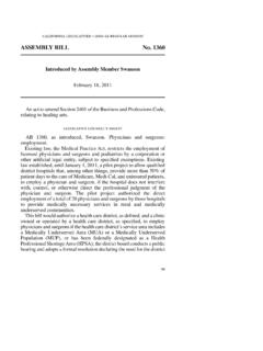
4 Offset Current to 15V80250nAIBI nput Bias Current to AenInput Noise Voltagef = 10kHz to 15V9nV/ HzinInput Noise Currentf = 10kHz to HzRINI nput ResistanceVCM = 12V 15V2050M Input ResistanceDifferential 15V5M CINI nput Capacitance 15V3pFInput Voltage Range + Voltage Range 15V 5V Mode Rejection RatioVCM = 12V 15V8692dBVCM = 5V7984dBVCM = Supply Rejection RatioVS = to 15V93105dB87654321 NULL IN+INV NCVOUTV+NULLTOP VIEWN8 PACKAGE, 8-LEAD PDIPT otal Supply Voltage (V+ to V ) .. 36 VDifferential Input Voltage(Transient Only) (Note 2).
5 10 VInput Voltage .. VSOutput Short Circuit Duration (Note 3) .. IndefiniteABSOLUTE MAXIMUM RATINGSWWWUO perating Temperature Range (Note 8) .. 40 C to 85 CSpecified Temperature Range (Note 9) .. 40 C to 85 CMaximum Junction Temperature (See Below)Plastic Package .. 150 CStorage Temperature Range .. 65 C to 150 CLead Temperature (Soldering, 10 sec) .. 300 CPACKAGE/ORDER INFORMATIONWUULT1360CN8 ORDER PARTNUMBERORDER PARTNUMBERTA = 25 C, VCM = 0V unless otherwise CHARACTERISTICS87654321 NULL IN+INV NCVOUTV+NULLTOP VIEWS8 PACKAGE, 8-LEAD PLASTIC SOConsult factory for Industrial and Military grade = 150 C, JA = 190 C/ WTJMAX = 150 C, JA = 130 C/ WLT1360CS8S8 PART MARKING1360(Note 1)
6 3LT1360 SYMBOLPARAMETERCONDITIONSVSUPPLYMINTYPMA XUNITSTA = 25 C, VCM = 0V unless otherwise CHARACTERISTICSAVOLL arge-Signal Voltage GainVOUT = 12V, RL = 1k = 10V, RL = 500 = , RL = 500 = , RL = 150 = 1V, RL = 500 SwingRL = 1k, VIN = 40mV VRL = 500 , VIN = 40mV VRL = 500 , VIN = 40mV VRL = 150 , VIN = 40mV VRL = 500 , VIN = 40mV VIOUTO utput CurrentVOUT = 13V 15V2634mAVOUT = 5V2129mAISCS hort-Circuit CurrentVOUT = 0V, VIN = 3V 15V4054mASRSlew RateAV = 2, (Note 5) 15V600800V/ s 5V250350V/ sFull Power Bandwidth10V Peak, (Note 6) Peak, (Note 6) Bandwidthf = 1 MHz 15V50 MHz 5V37 MHz , tfRise Time, Fall TimeAV = 1, 10%-90%, = 1, 15V35% 5V27%Propagation Delay50% VIN to 50% VOUT, Time10V Step, , AV = 1 15V60ns10V Step, , AV = 1 15V90ns5V Step, , AV = 1 5V65nsDifferential Gainf = , AV = 2, RL = 150 = , AV = 2, RL = 1k Phasef = , AV = 2, RL = 150 = , AV = 2, RL = 1k ResistanceAV = 1, f = 1 MHz ISSupply Current Offset Voltage(Note 4) VOS Drift(Note 7)
7 To 15Vl912 V/ CIOSI nput Offset Current to 15Vl350nAIBI nput Bias Current to ACMRRC ommon Mode Rejection RatioVCM = 12V 15Vl84dBVCM = 5Vl77dBVCM = Supply Rejection RatioVS = to 15Vl91dBAVOLL arge-Signal Voltage GainVOUT = 12V, RL = 1k = 10V, RL = 500 = , RL = 500 = , RL = 150 = 1V, RL = 500 SwingRL = 1k, VIN = 40mV VRL = 500 , VIN = 40mV VRL = 500 , VIN = 40mV VRL = 150 , VIN = 40mV VRL = 500 , VIN = 40mV VIOUTO utput CurrentVOUT = 15Vl25mAVOUT = 5Vl20mAISCS hort-Circuit CurrentVOUT = 0V, VIN = 3V 15Vl32mASRSlew RateAV = 2, (Note 5) 15Vl475V/ s 5Vl185V/ sISSupply Current CHARACTERISTICSThe l denotes the specifications which apply over the temperature range0 C TA 70 C, VCM = 0V unless otherwise 1: Absolute Maximum Ratings are those values beyond which the lifeof a device may be 2: Differential inputs of 10V are appropriate for transient operationonly, such as during slewing.
8 Large, sustained differential inputs will causeexcessive power dissipation and may damage the part. See InputConsiderations in the Applications Information section of this data sheetfor more 3: A heat sink may be required to keep the junction temperaturebelow absolute maximum when the output is shorted 4: Input offset voltage is pulse tested and is exclusive of warm-up 5: Slew rate is measured between 10V on the output with 6V inputfor 15V supplies and 2V on the output with input for 5V Offset Voltage(Note 4) VOS Drift(Note 7) to 15Vl912 V/ CIOSI nput Offset Current to 15Vl400nAIBI nput Bias Current to ACMRRC ommon Mode Rejection RatioVCM = 12V 15Vl84dBVCM = 5Vl77dBVCM = Supply Rejection RatioVS = to 15Vl90dBAVOLL arge-Signal Voltage GainVOUT = 12V, RL = 1k = 10V, RL = 500 = , RL = 500 = , RL = 150 = 1V, RL = 500 SwingRL = 1k , VIN = 40mV VRL = 500 , VIN = 40mV VRL = 500 , VIN = 40mV VRL = 150 , VIN = 40mV VRL = 500 , VIN = 40mV VIOUTO utput CurrentVOUT = 15Vl24mAVOUT = 5Vl20mAISCS hort-Circuit CurrentVOUT = 0V.
9 VIN = 3V 15Vl30mASRSlew Rate AV = 2, (Note 5) 15Vl450V/ s 5Vl175V/ sISSupply Current 6: Full power bandwidth is calculated from the slew ratemeasurement: FPBW = SR/2 7: This parameter is not 100% 8: The LT1360C is guaranteed functional over the operatingtemperature range of 40 C to 85 9: The LT1360C is guaranteed to meet specified performance from0 C to 70 C. The LT1360C is designed, characterized and expected tomeet specified performance from 40 C to 85 C, but is not tested or QAsampled at these temperatures. For guaranteed I-grade parts, consult CHARACTERISTICSThe l denotes the specifications which apply over the temperature range 40 C TA 85 C, VCM = 0V unless otherwise noted.
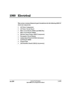
10 (Note 9)6LT1360 TYPICAL PERFORMANCE CHARACTERISTICS UWSupply Current vs Supply Voltageand TemperatureInput Common Mode Range vsSupply VoltageInput Bias Current vsInput Common Mode VoltageSUPPLY VOLTAGE ( V)1 SUPPLY CURRENT (mA)32654105015201360 G01 55 C25 C125 CINPUT COMMON MODE VOLTAGE (V)0 INPUT BIAS CURRENT ( A) 15 10010155 51360 G03VS = 15 VTA = 25 CIB = IB+ + IB 2 SUPPLY VOLTAGE ( V)V COMMON MODE RANGE (V) + G02TA = 25 C VOS < 1mVInput Bias Current vsTemperatureOpen-Loop Gain vsResistive LoadOutput Voltage Swing vsLoad CurrentOpen-Loop Gain vs TemperatureOutput Voltage Swing vsSupply VoltageTEMPERATURE ( C)0 INPUT BIAS CURRENT ( A) 50 2525100125507501360 G04VS = 15 VIB = IB+ + IB 2 LOAD RESISTANCE ( )1060 OPEN-LOOP GAIN (dB)658510010k1360 G0675701k80VS = 5 VVS = 15 VTA = 25 CFREQUENCY (Hz)101 INPUT VOLTAGE NOISE (nV/ Hz) CURRENT NOISE (pA/ Hz)110en1k100100k10k1360 G05VS = 15 VTA = 25 CAV = 101RS = 100kInput Noise Spectral DensitySUPPLY VOLTAGE ( V)