Transcription of First Watt F6 Power Amplifier
1 First Watt F6. Power Amplifier Owner's Manual Setup and Operation The initial setup of the Amplifier is very straight-forward. Place the Amplifier in a well-ventilated location, as it draws about 180 watts during operation and requires as much opportunity to cool itself as possible. You should be able to put your hands on the heat sink during operation. If you can't do this for 5. seconds or so, they need more ventilation. On the front panel there are two blue LED lights, one for each channel, indicating Power to each channel. If the light is on, the Power supply for that channel is delivering voltage. On the rear panel you will find pairs of RCA. inputs, speaker outputs, a fuse holder, an AC Power receptacle, and on/off switch and a label. The label will indicate a serial number and also what AC line voltage the Amplifier is set for. If the voltage is 120 VAC, then the fuse value will be a 3AG. slow blow fuse rated at amps. If the voltage is 240 VAC, then the fuse will be rated at amps.
2 Do not substitute a larger value fuse. Contact First Watt if you have any questions, or if you need a replacement fuse and can't find one locally. I'm assuming that you know how to attach the speaker cables to the 5 way output connectors provided. I recommend that you make all the connections with the Amplifier Power switch in the OFF position, my concern being mostly for the safety of any fragile loudspeaker driver you might be using. With everything connected up and the source equipment powered up First , you can proceed to turn on the Power switch to the Amplifier . Turn-on and turn-off thumps and noise are small in this Amplifier , and should not present any hazard to delicate drivers. The Amplifier takes a little less than a minute to Power up. Do not be alarmed if you don't hear music immediately. The Amplifier will warm up over the course of an hour or so, and will be at its best after that amount of time has elapsed. If you have any questions, contact First Watt (I answer all emails, but occasionally get backed up, so sometimes patience is required).
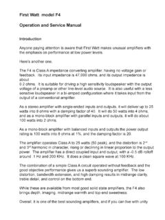
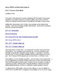
3 F6 Design and Philosophy By Nelson Pass The F6 is a very interesting Amplifier , First designed in 2012 and presented in October at the Burning Amp Festival in San Francisco. The transcript of my presentation there is available on the First Watt website under articles - F6 Talk at Burning Amp Festival 2012, and contains numerous comments and details about the original design, some of which are repeated here. The Amplifier was not initially slated for commercial production, and I continued to refine the design over the course of the next year and a half, working with different parts and adjustment values until both I and my listeners were satisfied that I had gotten the most out of this topology. The F6 is a very simple Class A push-pull design which uses N channel Power Fets driven by a high quality line level transformer which splits and isolates the drive signal to the output stage while also serving as the feedback element for the Amplifier . In this way loop feedback operates locally over a single gain stage: You can see from the simplified schematic that two parallel primary coils of the input transformer see the input signal on the left and feedback signal from the right.
4 They drive the Gates of the output Power Mosfets in what is known as Common Source mode, where this single stage provides both the voltage and current gain of the Amplifier . The Fets are biased up by regulated DC reference voltages which in this diagram are the circles with the little V inside. The output devices are operated in Square Law Class A where the conducted current is a square function of the Gate-Source voltage. With a constant bias voltage, this creates a Class A operating envelope for the output stage which allows both halves to remain in healthy forward conduction for output currents about three times the bias figure, resulting in an approximate doubling of Class A output Power . The bias of the F6 is high enough to reach the 25 watt Class A figure even without the square law effect, but it is helpful in delivering more current at lower distortion into lower impedance loads. Keep in mind that this not some fancy bias circuit this is what push-pull Class A Fets do naturally if you don't saddle them with the usual ballast resistors.
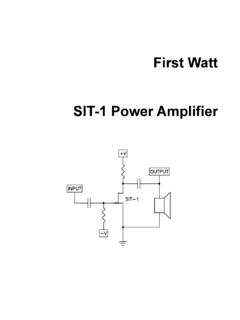
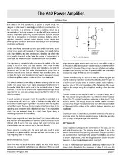
5 Here is a graphic which shows the current flowing through a single output transistor at 20 watts rms (40 watt peak) where there is still about 30% of the bias current flowing at minimum: We are trying for the smooth curves which give rise to easily-cancelled second harmonics via push-pull operation. I like to think that the rational cutoff figure for Class A operation with this sort of approach is a minimum current of about 5% or 10% of the bias figure. Apart from marketing, there is little point in trying to claim Class A operation when the current of the less-used half of the output stage is operating at micro-amps. We can contrast this with the curve of a Class AB push-pull stage, where each side of the output stage alternately makes an abrupt transition: The shape of this waveform gives rise to higher order harmonics, in this case beyond tenth order. Much of the performance of the F6 hinges on the quality of the transformer used for input and feedback.
6 Most commercially available transformers will not do this job at all (much less well), and I settled on a very high quality line-level transformer made by Jensen. The schematic presented is labeled simplified but the real one is not much more complicated. Much of the additions are simply the parts to create the reference DC voltages needed to bias the output devices and four potentiometers used to trim the bias and create the specific gain matching characteristics required for the output stage. Also I have employed a pair of input Jfet followers to buffer the transformer for high input impedance so that the transformer performance will not be degraded by preamplifiers having more than 100 ohms output impedance. They are the much lusted after NOS Toshiba 2SK170 and 2SJ74. I mentioned the specific matching between the output Power Fets used. This is to insure that the open-loop output distortion characteristic has a specific value and phase position of second and third harmonics for each point on the output Power curve.
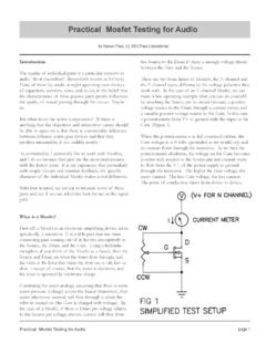
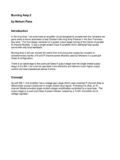
7 A lot of listening time was expended getting exactly the right character out of the original developmental F6. Each channel in production is adjusted for conformity to this original, and an extensive burn-in and computerized measurement (performed by yours truly) guarantees you the same experience. This is an example of what we see in test: Here is the distortion waveform at 1 watt showing a second harmonic at and a residual amount of third harmonic. The two output devices are adjusted so that every Amplifier will look just like this. This is not an Amplifier which emphasizes specifications, although the specifications are good. There are other products that measure better. What is important here is the manner in which these numbers are achieved and the value it brings to the listening experience. It is easy to make an Amplifier that measures well, but more difficult to make one that sounds subjectively exceptional to discerning listeners and does so reliably.
8 On the other hand, graphs are cheap, so here's some more: OK, so we got that out of the way, although there is still a summary of specifications toward the end, along with the usual warnings page. As I said at the beginning, this has been an interesting Amplifier to develop, largely because it has contributed to my depth of knowledge as to what techniques make for a good sounding Amplifier . Of course this is a subjective thing, and no Amplifier is the best for all listeners and situations. Any designer will always find himself narrow casting to the taste of a minority of potential customers, and I believe that if you can ever get a significant segment of the users to like your product, then that is as successful as you can ever hope for. In any case I have to assume that there is an audience whose taste resembles mine, and that if I like the sound of an Amplifier , then there will be a reason to build some more of them. I am not going to list all the usual audiophile buzzwords about what sounds good, rather I will list the guidelines that help get us there.
9 Besides measuring reasonably well, the best sounding amplifiers: tend to be simple are intrinsically linear run deep Class A. use high quality components The best sounding amplifiers also pay close attention to: the amount and scope of loop feedback the use of degeneration (the other feedback) and output loading the balance between types of feedback the amount and character of distortion harmonics vs level and frequency the appropriateness of gain devices for a given topology This last item makes for an interesting story because the F6 started out as a very nice Amplifier using the SemiSouth R100 enhancement-mode Power Jfets. While SemiSouth is no more, I have an adequate stock to support production, and I originally thought to use them for this. However I was in no hurry to get it out, and so had the time to play around with other gain devices, including the R085 depletion-mode Jfets and the SIT-1 transistors. It was surprising that the R085 and SIT transistors did not perform as well since they had done a little bit better job than the R100's in single-ended circuits.
10 By this I mean that people did not like the sound as much the specs were ok. The primary difference is that the R100 has a higher Drain impedance, that is to say that it behaves more like a voltage controlled current source, where the other parts behave a bit more like voltage controlled resistors. In tube vernacular you would say that the R100 is Pentode-like and the others were more Triode-like . The single-ended J2 and SIT-1 amplifiers are fine examples where the best performance is obtained by low impedance Drain types of transistors, and in both cases they are fed current by (relatively) distortion-free current sources in the case of the SIT-1 a big Power resistor. Meanwhile, I have examples of push- pull circuits where the Pentode-like devices are preferred. This of course led me back toward a device more like a Pentode than the R100, of which the IRFP240 is a fine example. Putting that device in this topology resulted in better sound, so it stayed.