Transcription of FUEL LEVEL GAUGE INSTALLATION INSTRUCTIONS
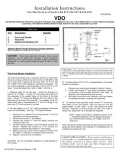
1 Gaugedashboardbracketnuts (knurled)Figure 1 GAUGE Mounting: do not install bracket and nuts until step LEVEL GAUGEINSTALLATION INSTRUCTIONS this fuel LEVEL GAUGE indicates the depth, not the amount, of fuel left in the fuel tank. because of the variety of fuel tank shapes, this universal GAUGE cannot compensate for the different rates that the fuel drops at various tank depths. IMPORTANT!This GAUGE is not designed as a direct replace-ment for factory gauges. It should be used only with our fuel LEVEL tank sender (SOLD SEPARATELY).The sender is not designed as a direct replace-ment for factory senders. It should be used only with our fuel LEVEL MAY REQUIRE the fuel LEVEL TANK SENDER INSTRUC-TIONS included with the sender for adjustment procedures that are required to complete the INSTALLATION . PRECAUTIONS1. read INSTRUCTIONS before observe all safety precautions contained in these INSTRUCTIONS and the INSTRUCTIONS for the fuel LEVEL tank drain fuel from the fuel tank into a safe, vented container and remove the fuel tank from the vehicle if any modifications to the tank are necessary.
2 Fill the tank with water to displace fuel vapors, then drain tank and dry disconnect the battery ground cable before performing any electrical route all wiring away from linkages, engine parts that become hot, or moving never smoke while working on your vehicle and always keep a fire extinguisher nearby. It should be rated for gas/chemical/electrical never lay tools on top of the battery or wear jewelry during electrical work to avoid severe electrical locate and operate gauges so that driving visibility is not temporary test connection before permanently mounting hardware or drilling GAUGE can be mounted into any surface or into a GAUGE pod. refer to Figure disconnect ground cable from battery before electrical work is choose a location to mount the GAUGE where it will be viewable from a normal driving If you are installing the GAUGE into a surface (for example the dashboard) make a 2-1/16 hole for the GAUGE .
3 Do not accidentally cut any wires or hoses. be sure there is clearance around the hole for the GAUGE mounting connect the blue and white wires using either Figure 2a or Figure 2b. Figure 2aFor Positive Dimmer ControlsgaugeblueWHITE dashLIGHTING togroundDIMMER controlto ground+12 VFigure 2bFor Negative Dimmer Controlsto groundDIMMER controldashLIGHTINGWHITE blue+12V+12 Vgauge GROMMETto FuseBOXF igure 3 GROUND WIRE andsenderto ground on FueltankGauge to Sender Connection5. read the fuel LEVEL tank sender INSTRUCTIONS and install the Refer to Figure 3. Route a length of 18- GAUGE insulated copper wire from the GAUGE to the sender. connect the wire to the sender. connect the other end of the wire to the connection post on the back of the GAUGE marked S .7. Make sure the fuel LEVEL sender is grounded to ground on fuel tank or to the same point as fac-tory Connect a second length of 18- GAUGE insulated copper wire to the connection post on the back of the GAUGE marked.
4 Connect the other end of the wire to the point where the fuel LEVEL tank sender is Connect a third length of 18- GAUGE insulated cop-per wire to the connection post on the back of the GAUGE marked + . Connect the other end of the wire to the fuse box where the wire will receive +12 volts of power whenever the ignition key is in a start, on or accessorY the mounting of the GAUGE . the battery ground sure that all water has been removed and the tank thoroughly dried before Refill the fuel tank, observing the GAUGE for proper operation as you the GAUGE indicates too low a fuel LEVEL compared to the actual LEVEL , re-check all connections, particularly the ground connections, as this will cause increased electrical resistance and false low the GAUGE does not indicate full or empty at the proper fuel levels , re-check the sender to make sure that the float arm moves freely between the two stop tabs on the GAUGESCUSTOM GAUGES