Transcription of General Description Applications - Microchip …
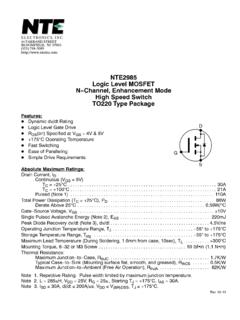
1 Supertex inc. # DSFP-TC7920 B080613TC7920 Features High voltage Vertical DMOS technology Integrated drain output high voltage diodes Integrated gate-to-source resistor Integrated gate-to-source Zener diode Low threshold, Low on-resistance Low input & output capacitance Fast switching speeds Electrically isolated N- and P-MOSFET pairsApplications High voltage pulsers Amplifiers Buffers Piezoelectric transducer drivers General purpose line drivers Logic level interfacesTwo Pair, N- and P-ChannelEnhancement-Mode MOSFET with Drain-DiodesGeneral DescriptionThe Supertex TC7920 consists of two pairs of high voltage, low threshold N- channel and P- channel MOSFETs in a 12-Lead DFN package.
2 All MOSFETs have integrated the output drain high voltage diodes, gate-to-source resistors and gate-to-source Zener diode clamps which are desired for high voltage pulser Applications . The complimentary, high-speed, high voltage, gate-clamped N and P- channel MOSFET pairs utilize an advanced vertical DMOS structure and Supertex s well-proven silicon-gate manufacturing process. This combination produces a device with the power handling capabilities of bipolar transistors and with the high input impedance and positive temperature coefficient inherent in MOS of all MOS structures, these devices are free from thermal runaway and thermally induced secondary breakdown. Supertex s vertical DMOS FETs are ideally suited to a wide range of switching and amplifying Applications where very low threshold voltage, high breakdown voltage, high input impedance, low input and output capacitance, and fast switching speeds are desired.
3 Typical Application Circuit to F +10V Supertex TC7920 DAMPVLGNDINCINDVSS+PULSE-PULSEENABVPP +100V 10nF Supertex MD1822 F F F VNN -100V 2 Supertex inc. # DSFP-TC7920 B080613TC7920 Absolute Maximum Ratings ParameterValueDrain-to-source voltageBVDSS Drain-to-gate voltageBVDGSO perating and storage temperature-55 C to +150 CAbsolute Maximum Ratings are those values beyond which damage to the device may occur. Functional operation under these conditions is not implied. Continuous operation of the device at the absolute rating level may affect device reliability. All voltages are referenced to device DFNP ackage MarkingPackage may or may not include the following marks.
4 Si , 4-layer, 3 x4 YWLL Y = Last Digit of Year SealedW = Code for Week SealedL = Lot Number = Green PackagingPin Configuration12-Lead DFN(top view)123456121110987SN1DN1DP1SP1DN2DP2GN 1GP1GN2SN2GP2SP2 Thermal Pad Typical Thermal ResistancePackage ja12-Lead DFN42OC/WOrdering InformationPart NumberPackage OptionPackingTC7920K6-G12-Lead DFN3000/ReelProduct SummaryBVDSS/BVDGSRDS(ON) (max) SymParameterMinTypMaxUnitConditionVRBrea kdown voltage200--VIR = 100 AVFF orward = 100mAIFMPark forward width = s, D% = 1%, One diodeIRReverse AVR = 100 V, TA = 25OC-100-VR = 100 V, TA = 125 OCtrrReverse recovery sIF = IR = 10mA, IRR = mA, RL = 100 Drain Output DiodesPin DescriptionPin #FunctionDescriptionPin #FunctionDescription1GN1 Gate of N-MOSFET 17DP2 Drain of P-MOSFET 22GP1 Gate of P-MOSFET 18DN2 Drain of N-MOSFET 23GN2 Gate of N-MOSFET 29SP1 Source of P-MOSFET 14SN2 Source of N-MOSFET 210DP1 Drain of P-MOSFET 15GP2 Gate of P-MOSFET 211DN1 Drain of N-MOSFET 16SP2 Source of P-MOSFET 212SN1 Source of N-MOSFET 1 Thermal PadDie attachment substrate, must be grounded externally3 Supertex inc.
5 # DSFP-TC7920 B080613TC7920N- channel Switching Waveforms and Test Circuit10%90%90%10%90%10% (ON)t(ON)td(OFF)t(OFF)10 VINPUT0 VVDDOUTPUT0VN- channel Electrical Characteristics (TA = 25 C unless otherwise specified) SymParameterMinTypMaxUnitsConditionsBVDS SD rain-to-source breakdown voltage200--VVGS = 0V, ID = (th)Gate threshold = VDS, ID = VGS(th)Change in VGS(th) with = VDS, ID = shunt resistor10-50K IGS = 100 AVZGSGate-to-source Zener voltage = gate voltage drain AVDS = Max rating, VGS = = Max Rating, VGS = 0V, TA = 125 OCID(ON)On-state drain = , VDS = = 10V, VDS = 50 VRDS(ON)Static drain-to-source on-state resistance--13 VGS = , ID = 150mA--10 VGS = 10V, ID = RDS(ON)Change in RDS(ON) with = , ID =150mAGFSF orward transconductance300--mmho VDS = 25V, ID = 500mACISSI nput capacitance-52-pFVGS = 0V,VDS = 25V, f = source output transfer (ON)Turn-on delay time--10nsVDD =25V, ID = ,RGEN = 25 trRise time--15td(OFF)Turn-off delay time--20tfFall time--15 VSDD iode forward voltage = 0V, ISD = 500mAtrrReverse recovery time-300-nsVGS = 0V, ISD = 500mANotes:1.
6 All parameters 100% tested at 25OC unless otherwise stated. (Pulse test: 300 s pulse, 2% duty cycle.)2. All parameters sample inc. # DSFP-TC7920 B080613TC7920P- channel Electrical Characteristics (TA = 25 C unless otherwise specified) SymParameterMinTypMaxUnitsConditionsBVDS SD rain-to-source breakdown voltage-200--VVGS = 0V, ID = (th)Gate threshold = VDS, ID = VGS(th)Change in VGS(th) with = VDS, ID = shunt resistor 10-50K IGS = 100 AVZGSGate-to-source Zener voltage = gate voltage drain current---10 AVDS = Max rating, VGS = = Max Rating, VGS = 0V, TA = 125 OCID(ON)On-state drain = , VDS = = -10V, VDS = -50 VRDS(ON)Static drain-to-source on-state resistance--15 VGS = , ID = -150mA--12 VGS = -10V, ID = RDS(ON)Change in RDS(ON)
7 With = -10V, ID =-200mAGFSF orward transconductance300--mmho VDS = -25V, ID = -500mACISSI nput capacitance-54-pFVGS = 0V, VDS = -25V, f = source output transfer (ON)Turn-on delay time--10nsVDD = -25V, ID = ,RGEN = 25 trRise time--15td(OFF)Turn-off delay time--20tfFall time--15 VSDD iode forward voltage = 0V, ISD = -500mAtrrReverse recovery time-300-nsVGS = 0V, ISD = -500mANotes:1. All parameters 100% tested at 25OC unless otherwise stated. (Pulse test: 300 s pulse, 2% duty cycle.)2. All parameters sample Switching Waveforms and Test (ON)t(ON)90%10%90%10%10%90%td(OFF)t(OFF) 0 VOUTPUTVDDS upertex inc. does not recommend the use of its products in life support Applications , and will not knowingly sell them for use in such Applications unless it receivesan adequate product liability indemnification insurance agreement.
8 Supertex inc. does not assume responsibility for use of devices described, and limits its liabilityto the replacement of the devices determined defective due to workmanship. No responsibility is assumed for possible omissions and inaccuracies. Circuitry andspecifications are subject to change without notice. For the latest product specifications refer to the Supertex inc. (website: ) 2013 Supertex inc. All rights reserved. Unauthorized use or reproduction is Bordeaux Drive, Sunnyvale, CA 94089 Tel: (The package drawing(s) in this data sheet may not reflect the most current specifications. For the latest package outline information go to )Doc.# DSFP-TC7920 B08061312-Lead DFN Package Outline (K6) body, height (max), pitch SymbolAA1A3bDD2EE2eLL1 Dimension(mm) not to Doc.
9 #: DSPD-12 DFNK64X4P050, Version Top ViewSide ViewBottom View AA1 DED2ebE2A3LL1 View B View B Note 1(Index AreaD/2 x E/2)Note 3 Note 2 Note 1(Index AreaD/2 x E/2)12 1121 Notes:1. A Pin 1 identifier must be located in the index area indicated. The Pin 1 identifier can be: a molded mark/identifier; an embedded metal marker; or a printed Depending on the method of manufacturing, a maximum of pullback (L1) may be The inner tip of the lead may be either rounded or square.