Transcription of H-bridge motor controller design using Nexperia discrete ...
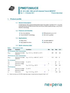
1 TN90002H-bridge motor controller design using Nexperia discretesemiconductors and logic ICsRev. 3 14 February 2020 Technical noteDocument informationInformationContentKeywordsH-b ridge, MOSFET, motor controllerAbstractAn example of a H-bridge motor controller designed with Nexperia discrete and Nexperia logic motor controller design using Nexperia discrete semiconductors and logic ICs1. IntroductionThis technical note demonstrates a H-bridge motor controller PCB, built using Nexperia discretesemiconductors and logic H-bridge circuit is a full bridge DC-to-DC converter allowing operation of a brushed DC motor (48 V max, 12 V min, 5 A max). The key feature of this design is that all electronic functions aredesigned with Nexperia discrete and logic IC components (low cost, no micro- controller or softwareneeded).MQ1Q2Q3Q4+V+Vaaa-030956 Fig. MOSFET H-bridge motor controlThe left MOSFETs of the full bridge (Q1 and Q3 in the simplified diagram above) are the switchingMOSFETs (see the PCB top view in Fig.)
2 26), the right MOSFETs (Q2 and Q4 in the simplifieddiagram above) select the motor rotation direction: right high side MOSFET fully ON = Forward right low side MOSFET fully ON = ReverseA switch selects the motor rotation select one of 3 switching frequencies: kHz, kHz or tactile push buttons allow the duty cycle ( motor speed) to be increased or decreased. Thereare 8 steps from 0 to 100% duty cycle. A current limitation protection avoids over current in themotor and MOSFETs (set at approximately A).This H-bridge motor controller PCB allows the user to choose between 3 Nexperia MOSFET packages (LFPAK33, LFPAK56D or LFPAK56), jumpers are used to connect the MOSFETs chosenby the technical note describes each of the main functions used in the information provided in this document is subject to legal disclaimers. Nexperia 2020. All rights reservedTechnical noteRev. 3 14 February 20202 / 38 NexperiaTN90002H-bridge motor controller design using Nexperia discrete semiconductors and logic ICs2.
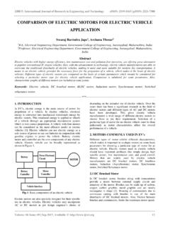
3 Block diagram and system functionalityOver-currentDetectionaaa-03 0969 ClockPWMD rivingCircuitryH-bridgeMotorPowerSupplyF ig. motor controller block Subsystems Supply Accepts 12 V to 48 V DC input Transient overvoltage protection Reverse polarity protection Buck converter (12 V) Linear regulator (5 V) for logic and duty cycle generator 4 MHz crystal oscillator and frequency divider to create 3 different switching frequencies Duty cycle sets by push button inputs to select the duty cycle (0% to 100%) kHz output is used to supply the charge pump on the driving circuitry Reset function to activate other function when VCC 5 V supply is stable Dead-time function and PWM enable (over current protection disabling) Level shifter Direction circuit High-side and low-side drivers to drive 4 MOSFETs of the full bridge Charge pump to supply the high-side Reservoir and decoupling capacitors Snubber on the left MOSFETs (switching MOSFETs)
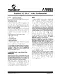
4 Jumper to connect the selected MOSFETs Gate drive resistors Low-side current detection Comparator, with voltage reference setting current limit PWM reset function reactivating PWM if fault disappearsTN90002 All information provided in this document is subject to legal disclaimers. Nexperia 2020. All rights reservedTechnical noteRev. 3 14 February 20203 / 38 NexperiaTN90002H-bridge motor controller design using Nexperia discrete semiconductors and logic ICs3. Subsystem Power supplyThe H-bridge motor controller power supply circuit comprises of: DC input stage with transient overvoltage and reverse voltage protection 12 V output DC-to-DC buck converter stage 5 V output linear regulator (for logic ICs) with status LEDR everse polarity protectionBuck converter 12 V outputDC Supply 12 V - 48 VLinear regulator,,,,LED 5 V OK12 V to 5 Vaaa-030910 Fig. supply circuitTransient overvoltage protectionD8 and D17 (PTVS60VS1 UTR) are transient voltage suppressor diodes, rated at 60 V, 400 W for a10/1000 s current pulse waveform.
5 They protect against positive and negative : These TVS diodes provide protection for transient overvoltage only - not for overvoltage protectionTN90002 All information provided in this document is subject to legal disclaimers. Nexperia 2020. All rights reservedTechnical noteRev. 3 14 February 20204 / 38 NexperiaTN90002H-bridge motor controller design using Nexperia discrete semiconductors and logic ICsReverse polarity protectionTwo parallel P-channel MOSFETs Q1 and Q2 (BUK6Y33-60P) form the reverse polarity and Q2 are biased on through D1 and D2 (BZX84J-B10) respectively when the supply polarityis positive (VGS= -10 V). Q1 and Q2 are off when the supply is negative (VGS = VF = V), currentcannot flow because the MOSFET body diodes are reverse means that if the supply is inverted, no current will flow into the circuit and potentially causedamage.,,,,aaa-030911 Fig. polarity protectionTN90002 All information provided in this document is subject to legal disclaimers.
6 Nexperia 2020. All rights reservedTechnical noteRev. 3 14 February 20205 / 38 NexperiaTN90002H-bridge motor controller design using Nexperia discrete semiconductors and logic ICsBuck converter (12 V)The next stage is a switching regulator that outputs 12 V. To start the switching regulator a start-up circuit is used consisting of: Zener diode D18 (BZX84J-B5V6), R10, and C14. This provides a5 V supply for inverting Schmitt trigger U21 (74HC1G14) before VCC (5 V) is available through D19(BAS316). U21 can then start the switching buck converter consists of: Q5 (BUK6Y33-60P), Schottky diode D6 (PMEG10030 ELP) andinductor L1. The output of the buck converter supplies the 12 V the output of U21 is high it turns on Q5 via the NPN transistor Q3 (BC846) and the NPN/PNP dual transistor pair Q4 (BC846 BPN). The voltage on node V_12 will then increase. When V_12 reaches 12 V, D3 ( BZX84J-B10) is conducting and there is enough voltage on U21 input toforce U21 output low.
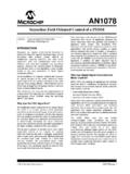
7 Then Q5 is switched off and the voltage at V_12 decreases until U21 inputis low enough to restart a new converterLinear regulator (5 V) for logic ICsA linear regulator comprising NPN transistor Q6 (BCP55), Zener diode D7 (BZX84J-B5V6) and R11provides a regulated VCC (5 V) rail for the logic regulatorTN90002 All information provided in this document is subject to legal disclaimers. Nexperia 2020. All rights reservedTechnical noteRev. 3 14 February 20206 / 38 NexperiaTN90002H-bridge motor controller design using Nexperia discrete semiconductors and logic Clock and duty cycle generatorThe Clock circuit comprises of: Crystal oscillator and frequency divider Duty cycle generator Frequency selection jumpersDuty cycle generatorFrequency selection jumpersClockaaa-030915 Fig. , duty cycle and frequency selectionTN90002 All information provided in this document is subject to legal disclaimers.
8 Nexperia 2020. All rights reservedTechnical noteRev. 3 14 February 20207 / 38 NexperiaTN90002H-bridge motor controller design using Nexperia discrete semiconductors and logic ICsCrystal oscillator and frequency dividerA crystal oscillator is used for accuracy and stability. The oscillator frequency is 4 (74 HCT4060) is a frequency divider, used to obtain different frequencies from the 4 MHz. Itprovides outputs at: kHz to drive the charge pump circuit (see Fig. 19) kHz, kHz and kHz for the switching frequency (user selectable)The switching frequency is selected by the multiplexer U3 (74 HCT151) according to the jumpersettings of JP7, JP8 and : Only one jumper should be fitted at the same switching frequency output is labeled Clock .A reset signal enables both multiplexer U3 and U19 (see next section for U19 explanation) whenVCC is 5 selection jumpersClockaaa-030937 Fig.
9 And frequency dividerTN90002 All information provided in this document is subject to legal disclaimers. Nexperia 2020. All rights reservedTechnical noteRev. 3 14 February 20208 / 38 NexperiaTN90002H-bridge motor controller design using Nexperia discrete semiconductors and logic ICsDuty cycle generatorSignals with a frequency 8 times higher than the required final switching frequencies are fed to 3 ofthe inputs of an 8-bit multiplexer IC, U19 (74 HCT151). These are labeled 8*Frequency_duty_cyclestep .Jumpers JP7, JP8, JP9 select both the switching frequency Clock and at the same time, Frequency_duty_cycle step which is a multiple (x8) of the switching higher frequency is used to create 8 duty cycle steps. Frequency_duty_cycle step goes into the clock input of programmable timer U18(74HC40103PW). U18 uses "Frequency_duty_cycle step as a output produce a duty cycle time in duty_cycle_output equals to the value read in input (P0to P3) multiplied by the clock period.
10 "duty_cycle_output is the general output of the Clock cycle generatoraaa-030938 Fig. cycleTable 1. Duty cycle selectionP0 (1)P1 (2)P2 (4)P3 (8)Duty Cycle00000% signal Clock from U3 resets U18 at each new switching period. When reset, U18 will readinputs P0 to P3 and output a duty cycle in duty_cycle_output proportional to the outputs of a 4-bit synchronous binary up/down counter U11 (74HC193) set the duty cyclevalue, it is the input of U18. Each time a rising edge appears on the UP input, the output value (Q0to Q3) increases by 1, each time a rising edge appears on the DOWN input, output value (Q0 toQ3) decreases by information provided in this document is subject to legal disclaimers. Nexperia 2020. All rights reservedTechnical noteRev. 3 14 February 20209 / 38 NexperiaTN90002H-bridge motor controller design using Nexperia discrete semiconductors and logic ICsThe push buttons SW3 and SW1 with U10 and U22 (74HC1G125) create the rising edges on UP orDOWN input of U11, when the user releases the push U11 output reaches a maximum count of 9 (8 to 9 transition), (Q0 and Q3 =1), the stop_up output of U12 (74HC1G08) is set to 1 and U10 (74HC1G125) is deactivated (high impedance), anyfurther impulses on SW3 can t produce a rising edge on UP input (U11) and the duty cycle reachesa U11 output reaches a minimum of 0 (Q0 to Q3 = 0), U17 (74HC1G08) stop_down outputis set to 1 and U22 (74HC1G125) is deactivated (high impedance), any further impulses on SW1can t produce a rising edge on DOWN input (U11)